Audi A4: Control Arm, Removing and Installing
Special tools and workshop equipment required
- Spreader Tool -3424-
- Torque Wrench 1332 40-200Nm -VAG1332-
- Engine and Gearbox Jack -VAS6931-
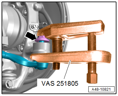
- Ball Joint Splitter -VAS251805-
- Engine/Gearbox Jack Adapter - Wheel Hub Support -T10149-
 Caution
This procedure contains mandatory replaceable parts. Refer to component overview and parts catalog prior to starting procedure.
Mandatory Replacement Parts
- Bolt/Nut - Control Arm to Subframe
- Bolt - Control Arm to Shock Absorber Fork
- Nut - Ball Joint to Control Arm
Removing
- Before starting the procedure, determine the curb weight position. Refer to → Chapter "Wheel Bearing in Curb Weight Position, Lifting Vehicles with Coil Spring".
- Remove the front wheel. Refer to → Chapter "Wheels and Tires".
- Remove the noise insulation. Refer to → Body Exterior; Rep. Gr.66; Noise Insulation; Noise Insulation, Removing and Installing.
- To protect the threads, remove the nut -arrow- from the tie rod end joint pin until it is flush with the joint pin threads.
 WARNING
There is a risk of injury from falling components.
When pressing off, the tie rod end loosens abruptly from the wheel bearing housing. Use, for example, the -VAS6931- to secure.
Caution
There is a risk of damaging the ball joint puller.
Make sure that both puller lever arms are parallel to each other when using maximum force.
- Remove the tie rod end with the -VAS251805- from the wheel bearing housing.
- Then remove the nut. Use a 6 mm inner hex socket to counterhold at the joint pin if necessary.
- Tie up the tie rod.
 Note
Note
To prevent the joints on the upper control arm from being damaged, support the wheel bearing housing against too strong rebound.
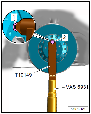
- Turn the wheel hub, until a wheel bolt hole is at the top.
- Install the -T10149- with a wheel bolt -2- on the wheel hub.
Note
Ignore item -1-.
- Support the wheel bearing housing over the -T10149- using the -VAS6931-.
WARNING
Risk of accident!
- Do not lift or lower the vehicle when the -VAS6931- is under the vehicle.
- Do not leave the -VAS6931- under the vehicle any longer than necessary.
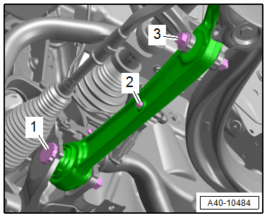
- Equipped on some models: remove the nut -2- and free up the coupling rod for the level control system sensor.
- Disconnect the threaded connections -1 and 3- for the control arm.
- Pivot the control arm toward the front.
Note
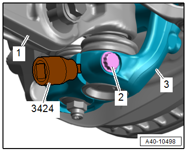
To remove the bolt -1-, push the steering all the way to the left or right.
- Remove the bolt -2-.
- Insert the -3424- into the slit on the wheel bearing housing -3- and turn 90º.
- Remove the control arm -1- with the ball joint.
Installing
Install in reverse order of removal and note the following:
- When reusing the ball joint, clean any remaining locking compound residue off the pin threads.
- Bring the control arm with the ball joint into the installation position.
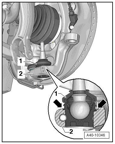
Caution
There is a risk of damage occurring in the threaded connection area on the wheel bearing housing if the installation position is incorrect.
Insert the ball joint -1- into the wheel bearing housing -2- up to the contact surface -arrows-.
- Install the threaded connections for the components with bonded rubber bushings only until the stop, but do not tighten yet.
Note
Bonded rubber bushings have a limited range of rotation. Only tighten the threaded connections for the suspension when the vehicle is in curb weight position.
- Lift the wheel bearing in curb weight position. Refer to → Chapter "Wheel Bearing in Curb Weight Position, Lifting Vehicles with Coil Spring".
- When tightening the threaded connection -1-, the control arm must be pressed toward the inside of the vehicle.
- Overview table for when an axle alignment is needed. Refer to → Chapter "Need for Axle Alignment, Evaluating".
- Adjust the headlamps. Refer to → Electrical Equipment; Rep. Gr.94; Headlamps; Headlamps, Adjusting.
- Driver assistance systems front camera, calibrating. Refer to → Chapter "Driver Assistance Systems Front Camera, Calibrating".
Tightening Specifications
- Refer to → Chapter "Overview - Lower Control Arm and Ball Joint"
- Refer to → Body Exterior; Rep. Gr.66; Noise Insulation; Overview - Noise Insulation.
- Refer to → Chapter "Wheels and Tires"
READ NEXT:
 Guide Link, Removing and Installing
Special tools and workshop equipment required
Torque Wrench 1332 40-200Nm -VAG1332-
Torque Wrench 1332 Insert - Ring Wrench - 21mm -VAG1332/7-
Engine and Gearbox Jack -VAS6931-
Puller - Ball Join
Control Arm Ball Bearing, Replacing
Control Arm Ball Bearing, Replacing, Wheel Bearing Housing Side
Special tools and workshop equipment required
Press Plate -VW402-
Press Piece - Multiple Use -VW412-
Press Piece - 42mm -VW516-
Pre
Ball Joint, Removing and Installing
Special tools and workshop equipment required
Torque Wrench 1332 40-200Nm -VAG1332-
Torque Wrench 1332 Insert - Ring Wrench - 21mm -VAG1332/7-
Ball Joint Splitter -T40277-
Caution
This p
SEE MORE:
Wheel Bearing in Curb Weight Position, Lifting Vehicles with Coil Spring
Special tools and workshop equipment required
Engine and Gearbox Jack -VAS6931-
Tensioning Strap -T10038-
Engine/Gearbox Jack Adapter - Wheel Hub Support -T10149-
Note
All bolts on chassis components with bonded rubber bushings
must be tightened in curb weight position. Refer to
→&nb
Overview - Navigation System
Overview - Navigation System, MMI Navigation, 7UF
7UF - Navigation
Information Electronics Control Module 1 -J794- with
integrated CD player/SD memory card reader/navigation system in
the glove compartment
SD card with navigation data
Front Information Display Control Head -J685-, display in
c
