Audi A4: Guide Link, Removing and Installing
Special tools and workshop equipment required
- Torque Wrench 1332 40-200Nm -VAG1332-
- Torque Wrench 1332 Insert - Ring Wrench - 21mm -VAG1332/7-
- Engine and Gearbox Jack -VAS6931-
- Puller - Ball Joint -T40043-
 Caution
This procedure contains mandatory replaceable parts. Refer to component overview and parts catalog prior to starting procedure.
Mandatory Replacement Parts
- Nut - Guide Link to Wheel Bearing Housing
- Bolt/Nut - Guide Link to Subframe
Removing
- Before starting the procedure, determine the curb weight position. Refer to → Chapter "Wheel Bearing in Curb Weight Position, Lifting Vehicles with Coil Spring".
- Remove the front wheel. Refer to → Chapter "Wheels and Tires".
- Remove the rear noise insulation. Refer to → Body Exterior; Rep. Gr.66; Noise Insulation; Noise Insulation, Removing and Installing.
- Remove the subframe shield and move it to the side. Refer to → Chapter "Subframe Shield, Removing and Installing".
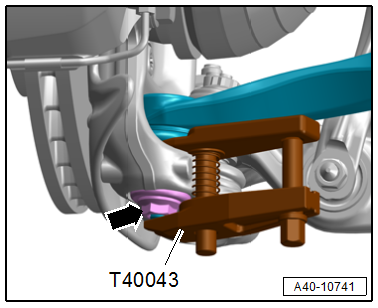
- To protect the threads, remove the nut -arrow- on the guide link joint pin until it is flush with the joint pin threads.
- Press out the guide link joint pin with the -T40043- from the conical seat. Do not damage the CV boot while doing so.
 WARNING
There is a risk of injury from falling components.
When pressing off, the guide link loosens abruptly from the wheel bearing housing. Use, for example, the -VAS6931- to secure.
- Remove the nut and free up the guide link on the wheel bearing housing. It may be necessary to counterhold the joint pin with a TX 40 socket to do this.
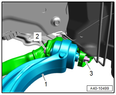
- Remove the nut -3- and bolt -2-.
- Remove the guide link -1-.
Installing
Install in reverse order of removal and note the following:
- When reusing the guide link, clean any locking compound residue off the pin threads.
- Install the threaded connections for the components with bonded rubber bushings only until the stop, but do not tighten yet.
 Note
Note
Bonded rubber bushings have a limited range of rotation. Only tighten the threaded connections for the suspension when the vehicle is in curb weight position.
- Lift the wheel bearing in curb weight position. Refer to → Chapter "Wheel Bearing in Curb Weight Position, Lifting Vehicles with Coil Spring".
- Overview table for when an axle alignment is needed. Refer to → Chapter "Need for Axle Alignment, Evaluating".
Tightening Specifications
- Refer to → Chapter "Overview - Lower Control Arm and Ball Joint"
- Refer to → Chapter "Overview - Subframe"
- Refer to → Body Exterior; Rep. Gr.66; Noise Insulation; Overview - Noise Insulation.
- Refer to → Chapter "Wheels and Tires"
READ NEXT:
 Control Arm Ball Bearing, Replacing
Control Arm Ball Bearing, Replacing, Wheel Bearing Housing Side
Special tools and workshop equipment required
Press Plate -VW402-
Press Piece - Multiple Use -VW412-
Press Piece - 42mm -VW516-
Pre
Ball Joint, Removing and Installing
Special tools and workshop equipment required
Torque Wrench 1332 40-200Nm -VAG1332-
Torque Wrench 1332 Insert - Ring Wrench - 21mm -VAG1332/7-
Ball Joint Splitter -T40277-
Caution
This p
SEE MORE:
Footrest, Removing and Installing
Removing
- Pry off the cap -3- with a small
screwdriver.
- Remove the bolt -2- underneath.
- Pull the footrest -1- downward in
the direction of -arrow- and remove
it.
Installing
Install in reverse order of removal.
Installation instructions: For example tightening
specifications,
Swerve assist
Applies to: vehicles with swerve assist
The swerve assist can help you to steer the vehicle
around an obstacle detected in a critical area.
If you avoid an obstacle after the acute warning,
then the swerve assist assists you by applying
slight steering adjustment to correct your steering
wheel angl
