Audi A4: Upper Transverse Link, Removing and Installing
Front Upper Transverse Link, Removing and Installing
Special tools and workshop equipment required
- Torque Wrench 1332 40-200Nm -VAG1332-
 Caution
This procedure contains mandatory replaceable parts. Refer to component overview and parts catalog prior to starting procedure.
Mandatory Replacement Parts
- Bolt - Front Upper Transverse Link to Subframe
- Bolt - Front Upper Transverse Link to Wheel Bearing Housing
Removing
- Before starting the procedure, determine the curb weight position. Refer to → Chapter "Wheel Bearing in Curb Weight Position, Lifting Vehicles with Coil Spring".
- FWD equipment version: Lower the subframe and do not remove the brake caliper and shock absorber while doing so. Refer to → Chapter "Subframe, Removing and Installing".
- AWD equipment version: Remove the subframe. Refer to → Chapter "Subframe, Removing and Installing".
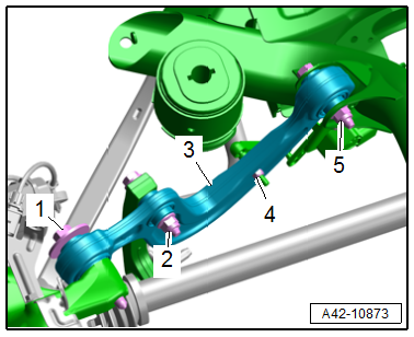
- Disconnect the threaded connections -2, 4 and 5-.
- Remove the bolt -1- and remove the upper transverse link -3-.
Installing
Install in reverse order of removal and note the following:
- Installation position. Refer to → Fig. "Transverse Link and Tie Rod Installation Position".
- Install the threaded connections up to the stop but do not tighten yet.
- Install the subframe. Refer to → Chapter "Subframe, Removing and Installing".
 Note
Note
Bonded rubber bushings have a limited range of rotation. Only tighten the threaded connections for the suspension when the vehicle is in curb weight position.
- Lift the wheel bearing in curb weight position. Refer to → Chapter "Wheel Bearing in Curb Weight Position, Lifting Vehicles with Coil Spring".
- Overview table for when an axle alignment is needed. Refer to → Chapter "Need for Axle Alignment, Evaluating".
- Adjust the headlamps. Refer to → Electrical Equipment; Rep. Gr.94; Headlamps; Headlamps, Adjusting.
- Driver assistance systems front camera, calibrating. Refer to → Chapter "Driver Assistance Systems Front Camera, Calibrating".
Tightening Specifications
- Refer to → Chapter "Overview - Transverse Link"
- Refer to → Chapter "Overview - Stabilizer Bar"
- Refer to → Chapter "Overview - Rear Level Control System Sensor"
Rear Upper Transverse Link, Removing and Installing
Special tools and workshop equipment required
- Torque Wrench 1332 40-200Nm -VAG1332-
Caution
This procedure contains mandatory replaceable parts. Refer to component overview and parts catalog prior to starting procedure.
Mandatory Replacement Parts
- Bolt - Rear Upper Transverse Link to Subframe
- Bolt - Rear Upper Transverse Link to Wheel Bearing Housing
Removing
- Before starting the procedure, determine the curb weight position. Refer to → Chapter "Wheel Bearing in Curb Weight Position, Lifting Vehicles with Coil Spring".
- FWD equipment version: Lower the subframe and do not remove the brake caliper and shock absorber while doing so. Refer to → Chapter "Subframe, Removing and Installing".
- AWD equipment version: Remove the subframe. Refer to → Chapter "Subframe, Removing and Installing".
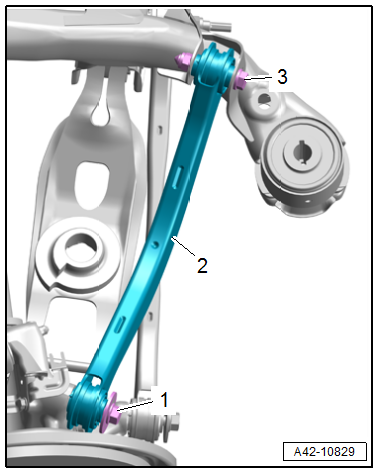
- Disconnect the threaded connection -3-.
- Remove the bolt -1- and remove the upper transverse link -2-.
Installing
Install in reverse order of removal and note the following:
- Installation position. Refer to → Fig. "Transverse Link and Tie Rod Installation Position".
- Install the threaded connections up to the stop but do not tighten yet.
- Install the subframe. Refer to → Chapter "Subframe, Removing and Installing".
Note
Bonded rubber bushings have a limited range of rotation. Only tighten the threaded connections for the suspension when the vehicle is in curb weight position.
- Lift the wheel bearing in curb weight position. Refer to → Chapter "Wheel Bearing in Curb Weight Position, Lifting Vehicles with Coil Spring".
- Overview table for when an axle alignment is needed. Refer to → Chapter "Need for Axle Alignment, Evaluating".
Tightening Specifications
- Refer to → Chapter "Overview - Transverse Link"
READ NEXT:
 Lower Transverse Link, Removing and Installing
Rear Lower Transverse Link, Removing and Installing
Special tools and workshop equipment required
Torque Wrench 1332 40-200Nm -VAG1332-
Engine and Gearbox Jack -VAS6931-
Engine/Gearbox Jack Adapte
Tie Rod, Removing and Installing
Special tools and workshop equipment required
Torque Wrench 1332 40-200Nm -VAG1332-
Engine/Gearbox Jack Adapter - Wheel Hub Support -T10149-
Engine and Gearbox Jack -VAS6931-
Caution
Thi
SEE MORE:
Hydraulic Pressure Sensor 1 -G545- and Hydraulic Pressure Sensor 2 -G546-,
Removing and Installing
Note
The Mechatronic remains installed.
WARNING
The system is under pressure.
The electronic ATF pump must be deactivated every
time before opening the transmission, and the hydraulic
pressure reservoir is drained.
Refer to
→ Chapter "ATF Pump, Deactivating and Draining
Overview - Telephone
Overview - Telephone, Bluetooth Hands-Free
Calling, 9ZX
The Information Electronics Control Module 1 -J794- is
installed with the Microphone Unit In Front Roof Module -R164-
and is exclusively for hands-free calling. The connection to the
Cellular Telephone -R54- takes place via Bluetooth.
The B
