Audi A4: Flushing Circuit Block Diagrams
 Note
Note
- The arrows in the following illustrations show the direction of refrigerant flow during flushing (refrigerant flows in opposite direction of flow when Air Conditioning (A/C) system is in operation while flushing, therefore the high pressure side of the A/C service system is connected to the low pressure connection of the refrigerant circuit to the A/C compressor).
- These block diagrams indicate a refrigerant circuit with restrictor and reservoir and a refrigerant circuit with expansion valve, receiver/dryer and a second evaporator (optional equipment on certain vehicles)
- Depending on the construction of the A/C service station, check valves may be installed between the refrigerant circuit and the A/C service station (to guarantee the correct direction of refrigerant flow during flushing).
Refrigerant Circuit with Restrictor and Reservoir
Note
On vehicles with a restrictor and reservoir, the restrictor and reservoir are removed, the lines disconnected for removing the restrictor are reconnected. The pipe connections to the removed reservoir are connected with each other via two adapters and the Refrigerant Circuits Adapter Set 2 - Adapter 31 -VAS6338/31- (from the Refrigerant Circuits Adapter Set 1 -VAS6338/1-).
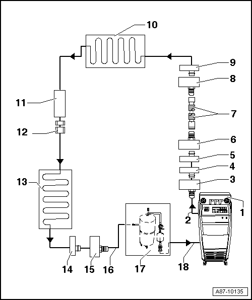
1 - A/C Service Station
- With electronics and a flushing program, for example A/C Service Station With Flushing Device. Refer to the Parts Catalog (Tools; Special Tools and Equipment: A/C and Heating).
- If an A/C service station without a flushing program is used, the procedure must be performed manually (evacuate, flush three times with at least 4 kg refrigerant each and extract refrigerant again, evacuate).
2 - A/C Service Station Refrigerant Hose
- From high pressure side of A/C service station (mostly colored red) to low pressure side connection of A/C compressor on refrigerant circuit (larger diameter).
3 - Adapter for Connecting Low Pressure Side to Refrigerant Circuit
- There are different versions depending on vehicle. Refer to → Chapter "Adapter for Assembling Flushing Circuit".
- From the Refrigerant Circuits Adapter Set 1 -VAS6338/1-
4 - Low Pressure Side Connection on Refrigerant Circuit
- There are different versions depending on vehicle. Refer to → Chapter "Adapter for Assembling Flushing Circuit".
- On refrigerant line from A/C compressor to reservoir
5 - Connection to Reservoir
- There are different versions depending on vehicle. Refer to → Chapter "Adapter for Assembling Flushing Circuit".
- On refrigerant line from A/C compressor to reservoir
6 - Adapter for Bridging the Removed Reservoir
- There are different versions depending on vehicle. Refer to → Chapter "Adapter for Assembling Flushing Circuit".
- From the Refrigerant Circuits Adapter Set 1 -VAS6338/1-
7 - Refrigerant Charge Hose
- Refer to → Chapter "Adapter for Assembling Flushing Circuit"
- For example Refrigerant Circuits Adapter Set 1 - Adapter 31 -VAS6338/31- (from the Refrigerant Circuits Adapter Set 1 -VAS6338/1-)
8 - Adapter for Bridging the Removed Reservoir
- There are different versions depending on vehicle. Refer to → Chapter "Adapter for Assembling Flushing Circuit".
- From the Refrigerant Circuits Adapter Set 1 -VAS6338/1-
9 - Connection to Reservoir
- There are different versions depending on vehicle. Refer to → Chapter "Adapter for Assembling Flushing Circuit".
10 - Evaporator
11 - Component Location of Restrictor
- Restrictor is removed.
- Remove the restrictor. Refer to → Heating, Ventilation and Air Conditioning; Rep. Gr.87; System Overview - Refrigerant Circuit (vehicle-specific repair manual).
12 - Bolts in Refrigerant Line
- Bolt together again after removing restrictor. Refer to → Heating, Ventilation and Air Conditioning; Rep. Gr.87; System Overview - Refrigerant Circuit (vehicle-specific repair manual).
13 - Condenser
14 - High Pressure Side Connection on Refrigerant Circuit
- There are different versions depending on vehicle. Refer to → Chapter "Adapter for Assembling Flushing Circuit".
15 - Adapter to Connection for High Pressure Side on Refrigerant Circuit
- There are different versions depending on vehicle. Refer to → Chapter "Adapter for Assembling Flushing Circuit".
- From the Refrigerant Circuits Adapter Set 1 -VAS6338/1-
16 - Charge Hose for Refrigerant Circuit Flushing Device
- From connection to the high pressure side of the A/C compressor on the refrigerant circuit (smaller diameter) to input of refrigerant circuit flushing device.
17 - Flushing Equipment for Refrigerant Circuits
- There are different versions of the Refrigerant Circuit Flushing Device. Refer to the Parts Catalog (Tools; Special Tools and Equipment: A/C and Heating).
- With filter, viewing glass, safety valve, heating, refrigerant container etc. (depending on version).
- Depending on the construction of the A/C service station and of refrigerant circuit flushing device, a check-valve may be installed at output of refrigerant circuit flushing device (to guarantee correct direction of refrigerant flow during flushing).
18 - A/C Service Station Refrigerant Hose
- From the low pressure side of the service station (mostly blue) to the output of the flushing device for refrigerant circuits.
Refrigerant Circuit with Expansion Valve, Receiver/Dryer and Second Evaporator
Note
- This block diagram shows a refrigerant circuit with expansion valve, receiver/dryer and second evaporator (optional equipment on certain vehicles).
- On vehicles with an expansion valve and receiver/dryer, the expansion valve is removed and replaced by an adapter. Depending on the vehicle, the receiver/dryer must also be removed and line connections to fluid reservoir be connected to each other by two adapters and a charge hose.
- On a vehicle with only one evaporator, components from -16- are not present or are not needed.
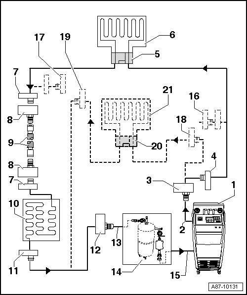
1 - A/C Service Station
- With electronics and a flushing program, A/C Service Station With Flushing Device. Refer to the Parts Catalog (Tools; Special Tools and Equipment: A/C and Heating).
- If an A/C service station without a flushing program is used, the procedure must be performed manually (evacuate, flush three times with at least 4 kg refrigerant each and extract refrigerant again, evacuate).
2 - A/C Service Station Refrigerant Hose
- From high pressure side of A/C service station (mostly colored red) to low pressure side connection of A/C compressor on refrigerant circuit (larger diameter).
3 - Adapter for Connecting Low Pressure Side to Refrigerant Circuit
- There are different versions depending on vehicle. Refer to → Chapter "Adapter for Assembling Flushing Circuit".
- From the Refrigerant Circuits Adapter Set 1 -VAS6338/1-
4 - Low Pressure Side Connection on Refrigerant Circuit
- There are different versions depending on vehicle. Refer to → Chapter "Adapter for Assembling Flushing Circuit".
5 - Adapter for the Removed Expansion Valve
- There are different versions depending on vehicle. Refer to → Chapter "Adapter for Assembling Flushing Circuit".
- From the Refrigerant Circuits Adapter Set 1 -VAS6338/1-
6 - Evaporator
7 - Connection to Receiver/Dryer
- There are different versions depending on vehicle. Refer to → Chapter "Adapter for Assembling Flushing Circuit".
- Neither installed on vehicles with dryer cartridge in receiver/dryer at condenser nor with receiver/dryer installed in condenser. Refer to → Heating, Ventilation and Air Conditioning; Rep. Gr.87; System Overview - Refrigerant Circuit (vehicle-specific repair manual).
8 - Adapter for Bridging the Removed Receiver/Dryer
- Not required for all vehicles.
- There are different versions depending on vehicle. Refer to → Chapter "Adapter for Assembling Flushing Circuit".
- From the Refrigerant Circuits Adapter Set 1 -VAS6338/1-
9 - Refrigerant Charge Hose
- Refer to → Chapter "Adapter for Assembling Flushing Circuit"
- For example Refrigerant Circuits Adapter Set 1 - Adapter 31 -VAS6338/31- (from the Refrigerant Circuits Adapter Set 1 -VAS6338/1-)
10 - Condenser
- If a receiver/dryer with dryer cartridge is installed at the condenser, the dryer cartridge must be removed (reseal receiver/dryer at or in condenser). Refer to → Heating, Ventilation and Air Conditioning; Rep. Gr.87; System Overview - Refrigerant Circuit or (vehicle-specific repair manual).
- If the receiver/dryer is directly installed at the condenser, the receiver/dryer must be removed and replaced only after flushing. Refer to → Heating, Ventilation and Air Conditioning; Rep. Gr.87; System Overview - Refrigerant Circuit (vehicle-specific repair manual).
Note
On certain vehicles the receiver/dryer is integrated inside the condenser and the dryer cartridge cannot be replaced separately and is not available as a single part. Replace the condenser with the receiver/dryer or dryer cartridge after flushing on these vehicles. Refer to → Heating, Ventilation and Air Conditioning; Rep. Gr.87; System Overview - Refrigerant Circuit and the Parts Catalog.
11 - High Pressure Side Connection on Refrigerant Circuit
- There are different versions depending on vehicle. Refer to → Chapter "Adapter for Assembling Flushing Circuit".
12 - Adapter to Connection for High Pressure Side on Refrigerant Circuit
- There are different versions depending on vehicle. Refer to → Chapter "Adapter for Assembling Flushing Circuit".
- From the Refrigerant Circuits Adapter Set 1 -VAS6338/1-
13 - Charge Hose for Refrigerant Circuit Flushing Device
- From connection to the high pressure side of the A/C compressor on the refrigerant circuit (smaller diameter) to input of refrigerant circuit flushing device.
14 - Flushing Equipment for Refrigerant Circuits
- There are different versions of the Refrigerant Circuit Flushing Device. Refer to the Parts Catalog (Tools; Special Tools and Equipment: A/C and Heating).
- With filter, viewing glass, safety valve, heating, refrigerant container etc. (depending on version).
- Depending on the construction of the A/C service station and of refrigerant circuit flushing device, a check-valve may be installed at output of refrigerant circuit flushing device (to guarantee correct direction of refrigerant flow during flushing).
15 - A/C Service Station Refrigerant Hose
- From the low pressure side of the service station (mostly blue) to the output of the flushing device for refrigerant circuits.
16 - Adapter to Seal Output to Second Evaporator
- Only necessary on certain vehicles with optional equipment "second evaporator"
- From the Refrigerant Circuits Adapter Set 1 -VAS6338/1-
17 - Adapter to Seal Output to Second Evaporator
- Only necessary on certain vehicles with optional equipment "second evaporator"
- From the Refrigerant Circuits Adapter Set 1 -VAS6338/1-
18 - Low Pressure Side Connection on Refrigerant Circuit to Second Evaporator
- There are different versions depending on vehicle. Refer to → Chapter "Adapter for Assembling Flushing Circuit".
- Only present on certain vehicles with optional equipment "second evaporator"
19 - Connection of High Pressure Side on Refrigerant Circuit to Second Evaporator
- There are different versions depending on the vehicle. Refer to → Chapter "Adapter for Assembling Flushing Circuit".
- Only present on certain vehicles with optional equipment "second evaporator"
20 - Adapter for the Removed Expansion Valve on Second Evaporator
- There are different versions depending on the vehicle. Refer to → Chapter "Adapter for Assembling Flushing Circuit".
- Only necessary on certain vehicles with optional equipment "second evaporator"
- From the Refrigerant Circuits Adapter Set 1 -VAS6338/1-
21 - Second Evaporator
- Only present on certain vehicles with optional equipment "second evaporator"
Vehicles with high-voltage system (without additional functions of the A/C system for example on the Audi A3 e-tron, Q5 hybrid etc.)
Note
- The refrigerant circuit is cleaned in two flushing cycles (first the section with the evaporator in the front heater and A/C unit and then the section with the high-voltage battery heat exchanger or the evaporator in the battery cooling module). Refer to → Chapter "Adapter for Assembling Flushing Circuit".
- On vehicles with two evaporators or an evaporator with a heat exchanger, disconnect second evaporator circuit from first evaporator circuit or to the evaporator via a hand shut-off valve and flush separately. Refer to → Chapter "Adapter for Assembling Flushing Circuit" and → Heating, Ventilation and Air Conditioning; Rep. Gr.87; System Overview - Refrigerant Circuit (vehicle-specific repair manual).
- The design of the different flushing circuits for this vehicle is similar to a vehicle with two evaporators.
Vehicles with a high-voltage system (with additional functions of the A/C system such as heat pump operation for example on the Audi Q7 e-tron etc.)
Note
- The refrigerant circuit is cleaned in multiple flushing cycles. Refer to → Chapter "Adapter for Assembling Flushing Circuit" and → Heating, Ventilation and Air Conditioning; Rep. Gr.87; Refrigerant Circuit (Cleaning the A/C system refrigerant circuit).
- To flush the refrigerant circuit is divided into multiple sections and then cleaned respectively in a flushing cycle. The division takes place by activating the installed electrically activated valves and via the installed manually activated hand shut-off valves. Refer to → Heating, Ventilation and Air Conditioning; Rep. Gr.87; Refrigerant Circuit (Cleaning the A/C system refrigerant circuit).
- The design of the different flushing circuits for these vehicles is described in the respective vehicle-specific repair manual. Refer to → Heating, Ventilation and Air Conditioning; Rep. Gr.87; Refrigerant Circuit (Cleaning the A/C system refrigerant circuit).
READ NEXT:
 Electrically Driven A/C Compressor, Rinsing (Remove Refrigerant Oil)
Vehicles with a High Voltage System (Hybrid Vehicles)
Extremely Dangerous Due to High-Voltage
The high-voltage system is under high-voltage. Death or serious
bodily injury by electric shock.
- I
Adapter for Assembling Flushing Circuit
Various adapters which are required to connect the Air
Conditioning (A/C) service station to the refrigerant circuit
for flushing and to bridge the removed receiver/dryer or
reservoir and expansi
SEE MORE:
Window Guide, Removing and Installing
Removing
- Remove the window frame trim panel. Refer to
→ Body Interior; Rep. Gr.70; Rear Door Trim Panels; Window Frame
Trim Panel, Removing and Installing.
- Remove the B-pillar trim. Refer to
→ Chapter "B-Pillar Door Trim, Removing and Installing, Rear".
-
Quick-Release Connections on Refrigerant Lines
WARNING
The quick-release coupling connectors may be
unlocked and opened only if the refrigerant circuit is
empty.
Note
This illustration shows the quick-coupling connection with a
refrigerant pipe with an inner heat exchanger that is installed
in the Audi A4 from MY 2008 and
