Audi A4: Door
Overview - Door
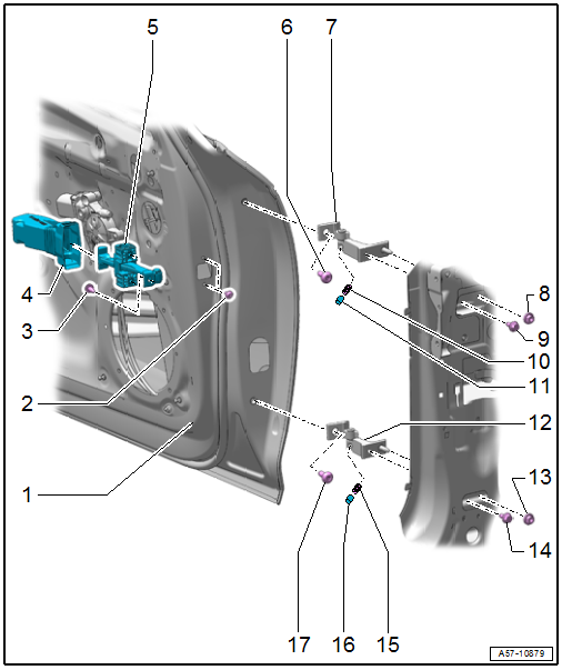
1 - Door
- Removing and installing. Refer to → Chapter "Door, Removing and Installing".
2 - Bolt
- 8 Nm
- Quantity: 2
3 - Bolt
- 33 Nm
4 - Cap
- For the door arrester
- Installation position. Refer to → Fig. "Cap Installation Position".
5 - Door Arrester
- Installation position. Refer to → Fig. "Door Arrester Installation Position".
- Removing and installing. Refer to → Chapter "Door Arrester, Removing and Installing".
6 - Bolt
- 45 Nm
7 - Upper Door Hinge
8 - Nut
- 32 Nm
9 - Bolt
- 32 Nm
10 - Set Screw
- 23 Nm
11 - Cap
12 - Lower Door Hinge
13 - Nut
- 32 Nm
14 - Bolt
- 32 Nm
15 - Set Screw
- 23 Nm
16 - Cap
17 - Bolt
- 45 Nm
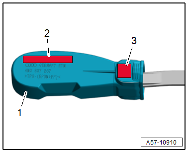
Cap Installation Position
In the installed position, the lettering on the cap -1- must be readable in the upper installation position.
2 - LEFT UPPER FRONT - left / RIGHT UPPER FRONT - right
3 - VL - left / VR - right
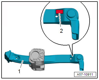
Door Arrester Installation Position
In the installed position, the lettering on the door arrester -1- must be readable in the upper installation position:
2 - VL - left / VR - right
Overview - Door Seals
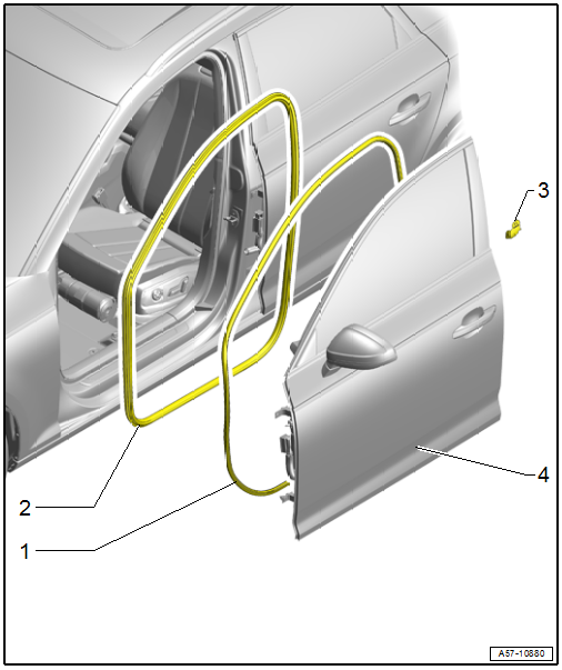
1 - Outer Door Seal
- Replace after removing
- Removing and installing. Refer to → Chapter "Outer Door Seal, Removing and Installing".
2 - Inner Door Seal
- Removing and installing. Refer to → Chapter "Inner Door Seal, Removing and Installing".
3 - B-Pillar Seal
4 - Door
- Removing and installing. Refer to → Chapter "Door, Removing and Installing".
READ NEXT:
 Door, Removing and Installing
Caution
This procedure contains mandatory replaceable parts.
Refer to component overview and parts catalog prior to
starting procedure.
Mandatory Replacement Parts
Outer Door Seal - from D
Door Arrester, Removing and Installing
Removing
- Move the door window into the "closed" position.
- Remove the door trim panel. Refer to
→ Body Interior; Rep. Gr.70; Front Door Trim Panels; Front Door
Trim Pan
Door Components
Overview - Window Regulator
1 -
Nut
7.5 Nm
2 -
Window Regulator
Removing and installing. Refer to
→ Chapter "Window Regulator, Removing and Installing".
3 -&nbs
SEE MORE:
Door Arrester, Removing and Installing
Removing
- Move the door window into the "closed" position.
- Remove the door trim panel. Refer to
→ Body Interior; Rep. Gr.70; Front Door Trim Panels; Front Door
Trim Panel, Removing and Installing.
- Remove the speaker. Refer to
→ Communication; Rep.
A/C Refrigerant High Pressure Switch -F23-
Note
Switch pressures, removing and installing switches as well
as switch arrangement and version. Refer to vehicle specific
refrigerant circuit
→ Heating, Ventilation and Air Conditioning; Rep. Gr.87; System
Overview - Refrigerant Circuit (vehicle-specific
repair manua
© 2019-2026 Copyright www.audia4b9.com
