Audi A4: Door, Removing and Installing
 Caution
This procedure contains mandatory replaceable parts. Refer to component overview and parts catalog prior to starting procedure.
Mandatory Replacement Parts
- Outer Door Seal - from Door
Removing
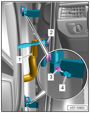
- Disconnect the door cut-off connector -1- from the A-pillar. Refer to → Electrical Equipment; Rep. Gr.97; Connectors.
- Tape off the A-pillar in the door arrester area using adhesive tape, so that the paint will not be damaged.
- Remove the door arrester bolt -2-.
- Remove the upper and lower cap -4-.
- Remove the set screw -3- from the upper and lower door hinge.
- Carefully remove the door upward out of the door hinges.
Installing
Install in reverse order of removal and note the following:
- Do not make any adjustments after installing the front door.
Tightening Specifications
- Refer to → Chapter "Overview - Door"
Door, Adjusting
Adjustment Dimensions
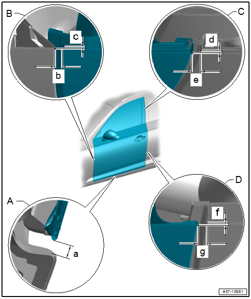
A - Front Door to Body
- Gap dimension -a- = 4.0 to 6.0 mm.
B - Front Door to Fender
- Gap dimension -b- = 2.9 to 4.2 mm
- Flush dimension -c- = 0/-1.0 mm
- Parallel alignment = 0.5 mm
C - Front Door to Top of Rear Door
- Gap dimension -e- = 2.8 to 4.8 mm
- Flush dimension -d- = +- 0.7 mm
- Parallel alignment = 0.9 mm
D - Front Door to Bottom of Rear Door
- Gap dimension -g- = 3.5 to 4.5 mm
- Flush dimension -f- = 0/-1.0 mm
- Parallel alignment = 0.5 mm
Door Adjustment, Checking
Special tools and workshop equipment required
- Gauge - Gap Adjustment -3371-
- Template -T40038/20-
- Adjustment dimensions. Refer to → Chapter "Adjustment Dimensions".
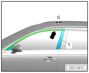
Door Adjustment, Checking using -T40038/20-:
- The door frame position is checked using the -T40038/20- at the following measuring point -arrow- at distance -c- from the B-pillar trim panel -1-.
- Dimension -c- = 100 mm.
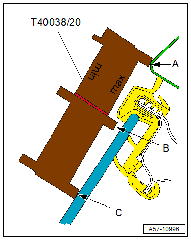
Side Adjustment, Checking using -T40038/20-:
Minimum Side Adjustment Tolerance, Checking
- Position the template on the body measuring point.
- "min" lettering on the template faces toward the vehicle.
- The template contact points -B and C- must rest on the door window.
- Point -A- should contact the roof edge, but a small gap is permitted.
- If point -A- does have a gap at the roof edge, the maximum tolerance must be checked.
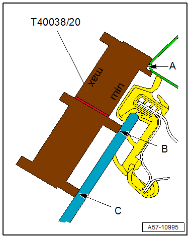
Maximum Side Adjustment Tolerance, Checking
- Position the template on the body measuring point.
- "max" lettering on the template faces toward the vehicle.
- The template contact points -A and C- must rest on the door window and on the roof edge.
- Contact point -B- may rest either on the door window, or there may be a gap.
- Adjustment is OK.
- If it is not OK, the door projects too far outward and must be adjusted.
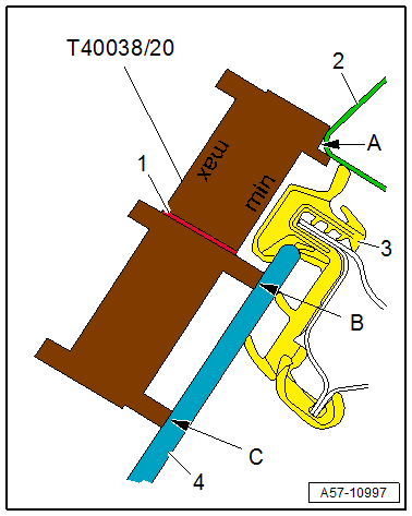
Height Adjustment, Checking using -T40038/20-:
- Position the template on the body measuring point.
- "min" lettering on the template faces toward the vehicle.
- Contact point -A- must rest against the side and bottom of the roof edge.
- The contact points -B and C- must be pressed against the door window -4-.
- For a proper height adjustment, the lower edge of the window guide -3- must be near the template marking -1-. Then the adjustment is correct.
- If not, the door must be adjusted.
Preliminary Work for Length and Side Adjustment
Driver Side
- Remove the Relay and Fuse Panel 1 -SR1-, free it up and push it to the side. Refer to → Electrical Equipment; Rep. Gr.97; Relay Panel, Fuse Panel, E-Boxes; Component Location Overview - Relay Panel, Fuse Panel and E-Boxes.
- Remove the mount for the Vehicle Electrical System Control Module -J519-. Refer to → Electrical Equipment; Rep. Gr.97; Control Modules; Vehicle Electrical System Control ModuleJ519, Removing and Installing.
- Free up the wiring harness.
Front Passenger Side
- Remove the glove compartment. Refer to → Body Interior; Rep. Gr.68; Storage Compartments and Covers; Glove Compartment, Removing and Installing.
- If equipped, remove the Relay and Fuse Panel 4 -SR4-. Refer to → Electrical Equipment; Rep. Gr.97; Relay Panel, Fuse Panel, E-Boxes; Component Location Overview - Relay Panel, Fuse Panel and E-Boxes.
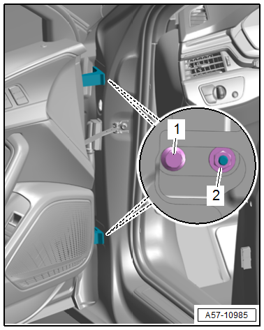
Length Adjustment
- Adjustment dimensions. Refer to → Chapter "Adjustment Dimensions".
Procedure
- Perform the preliminary work for length adjustment. Refer to → Chapter "Preliminary Work for Length and Side Adjustment".
- Loosen the bolts -1- and nuts -2- on the A-pillar.
- Adjust the door lengthwise.
- Tighten the bolts and nuts.
Tightening Specifications
- Refer to → Chapter "Overview - Door"
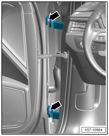
Side Adjustment
- Adjustment dimensions. Refer to → Chapter "Adjustment Dimensions".
Procedure
- Perform the preliminary work for the side adjustment. Refer to → Chapter "Preliminary Work for Length and Side Adjustment".
- Loosen the bolts -arrows- on the upper and lower hinge.
- Adjust the door to the center of the vehicle.
- Tighten the bolts.
Tightening Specifications
- Refer to → Chapter "Overview - Door"
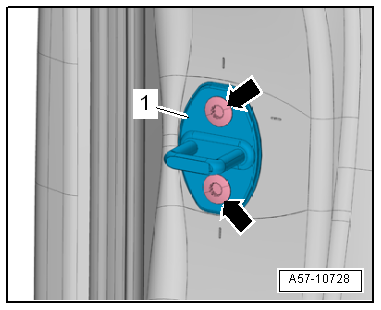
Striker, Adjusting
- Adjustment dimensions. Refer to → Chapter "Adjustment Dimensions".
Procedure
- Loosen the bolts -arrows-.
- Slide the striker -1- until the door is flush with the body contour.
- When adjusting the striker, move it only toward the center of the vehicle.
- Do not adjust the door height using the striker because the door lock will be damaged.
- When adjusted correctly, the striker must engage in the center of the door lock.
- Tighten the bolts.
Tightening Specifications
- Refer to → Chapter "Overview - Door Handle and Door Lock"
READ NEXT:
 Door Arrester, Removing and Installing
Removing
- Move the door window into the "closed" position.
- Remove the door trim panel. Refer to
→ Body Interior; Rep. Gr.70; Front Door Trim Panels; Front Door
Trim Pan
Door Components
Overview - Window Regulator
1 -
Nut
7.5 Nm
2 -
Window Regulator
Removing and installing. Refer to
→ Chapter "Window Regulator, Removing and Installing".
3 -&nbs
Window Regulator, Removing and Installing
Removing
- Remove the door window. Refer to
→ Chapter "Front Door Window, Removing and Installing".
- Release the retainers -1 and 3- on
the window regulator threaded pins -2-
usin
SEE MORE:
Audi adaptive cruise
control
General information
Applies to: vehicles with Audi adaptive cruise control
Depending on vehicle equipment, Audi adaptive
cruise control may consist of the following functions:
Within the limits of the system, the adaptive
speed and distance control assists the driver in
controlling the speed and the
A-Pillar Trim Panel, Removing and Installing
Special tools and workshop equipment required
Trim Removal Wedge -3409-
Lever - Fuel Line -T10468-
Omega Clip Tool -T40280-
Caution
This procedure contains mandatory replaceable parts.
Refer to component overview and parts catalog prior to
starting procedure.
Mandatory Replacement Pa
