Audi A4: Active Steering Safety Lock (Locking Solenoid), Removing and Installing
Special tools and workshop equipment required
- Vehicle Diagnostic Tester
- Torque Wrench 1783 - 2-10Nm -VAG1783-
Removing
 Note
Note
- To avoid a crooked steering wheel, the steering wheel must not be turned and the straight-ahead position or angle of the front wheels must not be changed when the adjusting element is removed.
- Follow the guidelines for clean working conditions. Refer to → Chapter "Guidelines for Clean Working Conditions".
- Turn the steering wheel in the straight position.
- Switch off the ignition.
- Remove the driver side instrument panel cover. Refer to → Body Interior; Rep. Gr.68; Storage Compartments and Covers; Driver Side Instrument Panel Cover, Removing and Installing.
- Mark the installation position of the Active Steering Safety Lock Actuator -F437--arrow- for reinstallation.
- Disconnect the connector -4-.
- Clean paint residue off the bolt heads.
- Remove the bolts -1 and 2- (use the socket included in the repair kit), and remove the safety lock -3- from the steering column.

Installing
Install in reverse order of removal and note the following:
- Place the adjusting element according to the mark applied during removal and tighten (use the socket included in the repair kit). Refer to → Fig. "Active Steering Safety Lock (locking solenoid) - Tightening Specification and Sequence".
- Erase the DTC memory.
- Perform an initialization movement - turn 45º to the left/right away from the straight-ahead position.
Function Test
Check the function of the steering during the road test and a fenced off area.
- Operating force
- Reset
- Play
- Noise
- Indicator lamp
- Read the DTC memory after the road test. There must be no entries in the DTC memory.
Tightening Specifications
- Refer to → Fig. "Active Steering Safety Lock (locking solenoid) - Tightening Specification and Sequence"
Steering Intermediate Shaft, Removing and Installing
Special tools and workshop equipment required
- Torque Wrench 1331 5-50Nm -VAG1331-
 Caution
This procedure contains mandatory replaceable parts. Refer to component overview and parts catalog prior to starting procedure.
Mandatory Replacement Parts
- Bolt - Steering Intermediate Shaft to Steering Gear
- Bolt - Steering wheel to Steering Column
Removing
- Bring wheels in the straight position.
- Move the driver seat all the way to the rear until it stops.
- Move the steering wheel as far to the rear and down as possible. Use the full steering column adjustment range for this.
- Switch off the ignition.
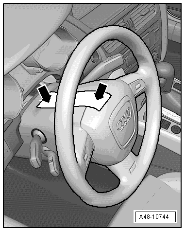
- Secure the steering wheel in the straight-ahead position using tape so that it does not turn unintentionally -arrow-.
Note
- Use adhesive tape that can be removed without leaving any adhesive residue.
- Be careful not to turn the steering wheel during the repair because the Airbag Spiral Spring/Return Spring with Slip Ring -F138- can become damaged.
- Remove the rear noise insulation. Refer to → Body Exterior; Rep. Gr.66; Noise Insulation; Noise Insulation, Removing and Installing.
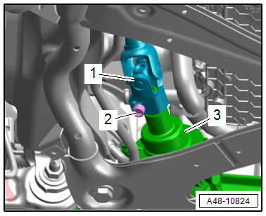
- Remove the bolt -2-.
- Remove the universal joint -1- for the steering intermediate shaft from the steering gear -3-.
- Remove the driver side footwell cover front section. Refer to → Body Interior; Rep. Gr.68; Storage Compartments and Covers; Driver Side Instrument Panel Cover, Removing and Installing.
- Remove the footrest. Refer to → Body Interior; Rep. Gr.70; Vehicle Interior Trim Panels; Footrest, Removing and Installing.
- Push the carpet slightly toward the rear.
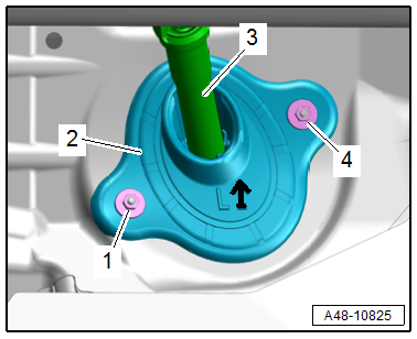
- Remove the nuts -1 and 4-, and remove the steering intermediate shaft -3- with the sealing lip -2-.
Note
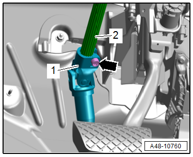
Ignore the -arrow-.
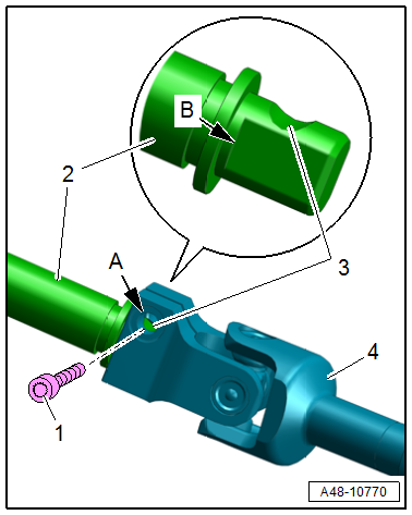
- Remove the bolt -arrow- and remove the steering intermediate shaft universal joint -1- from the steering column -2-.
- Remove the steering intermediate shaft.
Note
The installation position pictured is for equipment versions without active steering.
Installing
Install in reverse order of removal and note the following:
Note
- Replace the bolts after removing them.
- Clean the threaded holes for the bolts on the universal joint using a thread tap, for example.
- Bring the steering intermediate shaft -3- as shown into the installation position. The sealing lip -2- must rest on the insulation.
- The -arrow- points upward.
- Tighten the nuts -1 and 4-.
 WARNING
There is a risk of accident due to an absence of traction if the steering intermediate shaft is installed incorrectly.
Pay attention to the installation position and installation instructions.
- Install the steering intermediate shaft universal joint -4- up to the stop -arrow B- on the steering column -2- or steering gear.
- The opening -3- on the steering column or steering gear must align exactly with the hole -arrow A- for the bolt -1- on the universal joint as shown.
- Install the new bolt all the way by hand.
- Check if the steering intermediate shaft is seated correctly by pulling. Tighten the bolt.
- Repeat the procedure on the lower universal joint to the steering gear.
- Readapting the end position of the steering gear. Refer to → Chapter "Steering Gear End Positions, Adapting".
Tightening Specifications
- Refer to → Chapter "Overview - Steering Column"
- Refer to → Body Exterior; Rep. Gr.66; Noise Insulation; Overview - Noise Insulation.
READ NEXT:
 Electronic Steering Column Lock Control Module -J764-, Removing and
Installing
Electronic Steering Column Lock Control Module -J764-, Removing and
Installing
Special tools and workshop equipment required
Torque Wrench 1783 - 2-10Nm -VAG1783-
Removing
- Remove the steering column from the instrument panel central
tube and place in the driver footwe
Overview - Steering Gear
Overview - Steering Gear
1 - Bolt
Replace after removing
Tightening specification -Item 2-
2 - Subframe Crossbrace
Overview. Refer to
→ Chapter "Overview - Subframe
SEE MORE:
Rear Lid
Overview - Rear Lid, Sedan
Overview - Rear Lid
1 -
Tension Spring
Quantity: 2
Removing and installing. Refer to
→ Chapter "Tension Spring, Removing and Installing".
2 -
Rear Lid Hinge Trim Panel
Removing and installing. Refer to
→ Body Interior; Rep. Gr
Electric Coolant Pump, Removing and Installing
Coolant Recirculation Pump -V50-, Removing and Installing
Special tools and workshop equipment required
Hose Clamps - Up To 25mm -3094-
Hose Clip Pliers -VAS6340-
Removing
- Remove the engine cover. Refer to
→ Servicing - 4-Cylinder 2.0L 4V TFSI Engine; Rep. Gr.10; Engine
