Audi A4: Overview - Steering Gear
Audi A4 (B9) 2016-2026 Service Manual / Chassis / Steering / Steering Gear / Overview - Steering Gear
Overview - Steering Gear
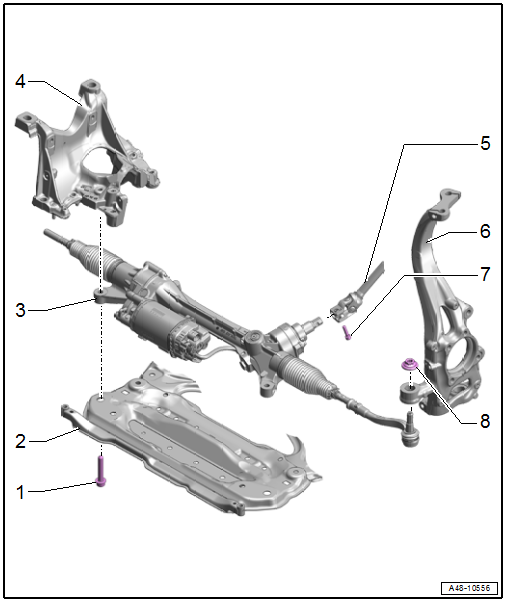
1 - Bolt
- Replace after removing
- Tightening specification -Item 2-
2 - Subframe Crossbrace
- Overview. Refer to → Chapter "Overview - Subframe".
3 - Steering Gear with Tie Rods
- With integrated Power Steering Control Module -J500-
- the Power Steering Control Module -J500- cannot be replaced separately
- Replace the steering gear if faulty
- Removing and installing. Refer to → Chapter "Steering Gear, Removing and Installing".
- Servicing. Refer to → Chapter "Overview - Steering Gear, Tie Rods".
4 - Subframe
- Overview. Refer to → Chapter "Overview - Subframe".
5 - Steering Intermediate Shaft
- Removing and installing. Refer to → Chapter "Steering Intermediate Shaft, Removing and Installing".
6 - Wheel Bearing Housing
- Overview. Refer to → Chapter "Overview - Wheel Bearing".
7 - Bolt
- Tightening specification -Item 1-
8 - Nut
- 140 Nm
- Replace after removing
- Remove the adhesive residue from the pin threads after removing
Overview - Steering Gear, Tie Rods
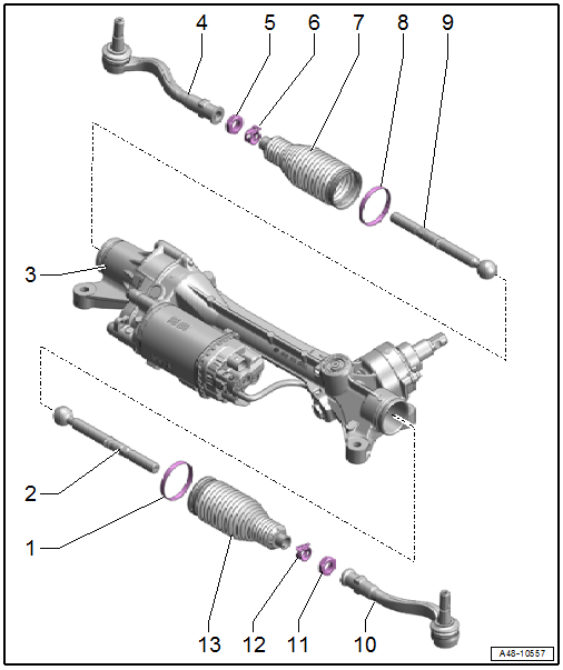
1 - Clamp
- Replace after removing
- Do not open the new clamp
- Tensioning.
2 - Tie Rod
- 140 Nm
- Grease the joint with Steering Gear Grease -G 052 168 A1-
- Removing and installing. Refer to → Chapter "Tie Rod, Removing and Installing".
3 - Steering Gear
- Grease the steering rack with Steering Gear Grease -G 052 168 A1-
- Removing and installing. Refer to → Chapter "Steering Gear, Removing and Installing".
4 - Tie Rod End
- Check dust cap for damage and correct seating.
- Check dimension. Refer to → Fig. "Tie Rod End Check Dimension"
- Removing and installing. Refer to → Chapter "Tie Rod End, Removing and Installing".
5 - Nut
- 80 Nm
- When loosening and tightening, counterhold at the tie rod end
6 - Spring Clamp
- Replace after removing
- Spring clamp, installing.
7 - Boot
- Check for damage
- Replace after removing
- Must not be twisted when toe is being adjusted
- Grease the sealing locations with Steering Gear Grease -G 052 168 A1-
- Replacing. Refer to → Chapter "Boot, Removing and Installing".
8 - Clamp
- Replace after removing
- Do not open the new clamp
- Tensioning. Refer to → Fig. "Tighten the Inner Clamp using the Locking Pliers -VAS6199-".
9 - Tie Rod
- 140 Nm
- Grease the joint with Steering Gear Grease -G 052 168 A1-
- Removing and installing. Refer to → Chapter "Tie Rod, Removing and Installing".
10 - Tie Rod End
- Check dust cap for damage and correct seating.
- Check dimension. Refer to → Fig. "Tie Rod End Check Dimension"
- Removing and installing. Refer to → Chapter "Tie Rod End, Removing and Installing".
11 - Nut
- 80 Nm
- When loosening and tightening, counterhold at the tie rod end
12 - Spring Clamp
- Replace after removing
- Spring clamp, installing. Refer to → Fig. "Outer Boot Installation Position".
13 - Boot
- Check for damage
- Replace after removing
- Must not be twisted when toe is being adjusted
- Grease the sealing locations with Steering Gear Grease -G 052 168 A1-
- Installation position. Refer to → Fig. "Outer Boot Installation Position".
- Replacing. Refer to → Chapter "Boot, Removing and Installing".
READ NEXT:
 Steering Gear, Removing and Installing
Special tools and workshop equipment required
Torque Wrench 1331 5-50Nm -VAG1331-
Torque Wrench 1332 40-200Nm -VAG1332-
Engine and Gearbox Jack -VAS6931-
Ball Joint Splitter -VAS251805-, not illu
Boot, Removing and Installing
Special tools and workshop equipment required
Torque Wrench 1331 5-50Nm -VAG1331-
Hose Clip Pliers -VAS6362-
Hose Clip Pliers -VAG1921-
Caution
This procedure contains mandatory replacea
Tie Rod, Removing and Installing
Special tools and workshop equipment required
Torque Wrench 1332 40-200Nm -VAG1332-
Torque Wrench Insert - Open Jaw -VAG1923-
Caution
This procedure contains mandatory replaceable parts.
SEE MORE:
Power luggage compartment cover
Applies to: vehicles with power luggage compartment cover
Fig. 76 Luggage compartment: retracted cover
Fig. 77 Luggage compartment: removing the luggage
compartment cover
Observe the safety precautions.
If you open the luggage compartment lid, the
power luggage compartment cover will move into
po
General Safety Precautions
As per VBG 20, German industrial liability insurance
association.
Pay attention to the workshop-specific instructions. It
should be kept in the workshop.
Product Characteristics
Refrigerants used in motor vehicle air conditioning systems
belong to the new generation of refrigerants based on
© 2019-2026 Copyright www.audia4b9.com
