Audi A4: Steering Gear, Removing and Installing
Special tools and workshop equipment required
- Torque Wrench 1331 5-50Nm -VAG1331-
- Torque Wrench 1332 40-200Nm -VAG1332-
- Engine and Gearbox Jack -VAS6931-
- Ball Joint Splitter -VAS251805-, not illustrated
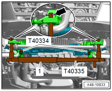
- Locating Pin -T40334-
- Support Brace -T40335-
 Caution
This procedure contains mandatory replaceable parts. Refer to component overview and parts catalog prior to starting procedure.
Mandatory Replacement Parts
- Nut - Steering Gear with Tie Rods to Wheel Bearing Housing
- Bolt - Steering Intermediate Shaft to Steering Gear with Tie Rods
- Bolts - Subframe Crossbrace/Steering Gear to Subframe
Removing
- Bring wheels in the straight position.
- Switch off the ignition.
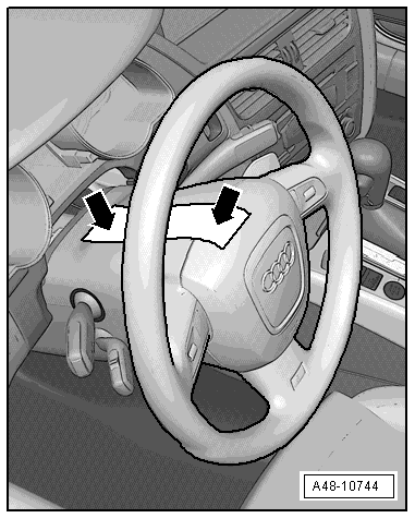
- Secure the steering wheel in the straight-ahead position using tape so that it does not turn unintentionally -arrow-.
 Note
Note
- Use adhesive tape, which can be removed without leaving any adhesive residue.
- Be careful not to turn the steering wheel during the repair because the Airbag Spiral Spring/Return Spring with Slip Ring -F138- can become damaged.
- Remove the front wheels. Refer to → Chapter "Wheels and Tires".
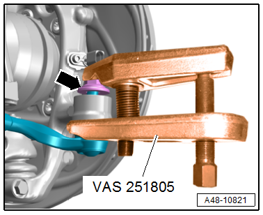
- To protect the threads, remove the nut -arrow- from the tie rod end joint pin until it is flush with the joint pin threads.
 WARNING
There is a risk of injury from falling components.
When pressing off, the tie rod end loosens abruptly from the wheel bearing housing. Use, for example, the -VAS6931- to secure.
Caution
There is a risk of damaging the ball joint puller.
Make sure that both puller lever arms are parallel to each other when using maximum force.
- Remove the tie rod end with the -VAS251805- from the wheel bearing housing.
- Then remove the nut. Use a 6 mm inner hex socket to counterhold at the joint pin if necessary.
- Repeat the procedure on the other side of the vehicle.
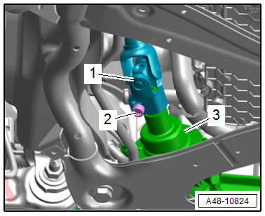
- Remove the bolt -2-.
- Remove the universal joint -1- for the steering intermediate shaft from the steering gear -3-.
- Lower the subframe crossbrace and do not press the guide link joint pin away from the conical seat while doing this. Refer to → Chapter "Subframe Crossbrace, Removing and Installing".
Caution
There is a risk of damaging the suspension components.
- If the subframe mount, the steering gear or the subframe crossbrace are not installed correctly, do not rest the vehicle on its wheels.
- The vehicle must not be supported on the subframe or the subframe crossbrace (for example using a floor jack).
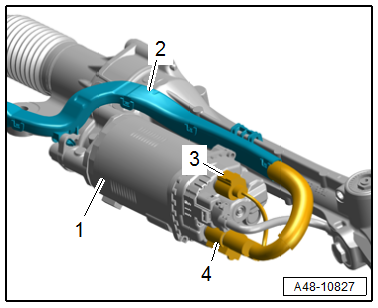
- Release the safety catch and push the retainer down to disconnect the connectors -3 and 4- from the Power Steering Control Module -J500-.
- Free up the wiring duct -2- for the wires on the steering gear -1-.
WARNING
There is an accident risk due to the weight of the steering gear.
A second technician is required to remove the steering gear.
- Insert the -T40335- on the left and right side into the subframe. If required, adjust the support brace at the knurled handle -1-.
- Secure the brace on the left and right side using a cotter pin -arrow-.
Caution
Risk of damaging the boot.
The steering gear must not contact the boots during removal.
- Remove the -T40334- and remove the steering gear.
Installing
Install in reverse order of removal and note the following:
- Install the subframe crossbrace. Refer to → Chapter "Subframe Crossbrace, Removing and Installing".
- Install the steering intermediate shaft. Refer to → Chapter "Steering Intermediate Shaft, Removing and Installing".
After installing a new steering gear with Power Steering Control Module -J500-, activate the control module.
- Connect the Vehicle Diagnostic Tester.
- Switch the ignition on.
- Select and start the Diagnostic operating mode.
- Select the Test plan tab.
- Select the Select individual test button and select the following tree structure consecutively:
- Chassis
- Steering
- 01 - OBD-capable systems
- 44 - Power Steering Control Module J500
- 44 - Power Steering Control Module Functions
- 44 - Control Module, Replacing
- Start the selected program and follow the instructions on the Vehicle Diagnostic Tester display.
- Overview table for when an axle alignment is needed. Refer to → Chapter "Need for Axle Alignment, Evaluating".
Tightening Specifications
- Refer to → Chapter "Overview - Steering Gear"
READ NEXT:
 Boot, Removing and Installing
Special tools and workshop equipment required
Torque Wrench 1331 5-50Nm -VAG1331-
Hose Clip Pliers -VAS6362-
Hose Clip Pliers -VAG1921-
Caution
This procedure contains mandatory replacea
Tie Rod, Removing and Installing
Special tools and workshop equipment required
Torque Wrench 1332 40-200Nm -VAG1332-
Torque Wrench Insert - Open Jaw -VAG1923-
Caution
This procedure contains mandatory replaceable parts.
Steering Gear End Positions, Adapting
Special tools and workshop equipment required
Vehicle Diagnostic Tester
Note
If the connection between the steering gear and the steering
wheel is disconnected, the end position of the ste
SEE MORE:
Belt Fastening Detection
Front Passenger Occupant Detection Sensor -G128-, Removing and Installing
Note
The passenger occupant detection sensor is only installed in the
front passenger seat.
Removing
- Unscrew the front passenger seat and tip to the rear with the
wires attached. Refer to
→ Chapter "Fr
Tachometer
The tachometer (1) displays the engine
speed in revolutions per minute (RPM). The beginning
of the red zone in the tachometer indicates
the maximum permissible engine speed for
all gears once the engine has been broken in. Before
reaching the red zone, you should shift into
the next higher gear, sel
