Audi A4: Overview - Telephone
Overview - Telephone, Bluetooth Hands-Free Calling, 9ZX
The Information Electronics Control Module 1 -J794- is installed with the Microphone Unit In Front Roof Module -R164- and is exclusively for hands-free calling. The connection to the Cellular Telephone -R54- takes place via Bluetooth.
The Bluetooth Antenna -R152- is integrated in the Information Electronics Control Module 1 -J794-.
9ZX - Bluetooth hands-free calling in the Information Electronics Control Module 1 -J794-
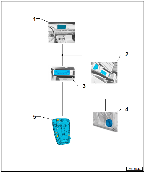
1 - Front Information Display Control Head -J685-, Display in Center of the Instrument Panel
2 - Multimedia System Control Head -E380- in the Center Console
3 - Information Electronics Control Module 1 -J794- with Bluetooth Antenna -R152- in the Glove Compartment
4 - Sound Systems
5 - Left Front Microphone -R140-, Microphone Unit in Front Roof Module -R164- in the Front Interior Lamp -W1-
Antennas
9ZX/EL0 - Bluetooth hands-free calling without connect:
- No Telephone Antenna -R65- is installed
- No LTE antennas (-R297-/-R306-) are installed
9ZX/EL3 - Bluetooth hands-free calling with connect:
- No Telephone Antenna -R65- is installed
- Europe and Rest of World (ER1/ER2): There are LTE antennas (LTE Antenna 1 -R297-/LTE Antenna 2 -R306-) installed, LTE Antenna 2 -R306- in the Roof Antenna -R216- and LTE Antenna 1 -R297- under the left rear bumper cover.
- USA (ER3): There are LTE antennas (LTE Antenna 1 -R297-/LTE Antenna 2 -R306-) installed, LTE Antenna 1 -R297- is under the left rear bumper cover and LTE Antenna 2 -R306- is under the right rear bumper cover.
Overview on Connect, LTE Antennas
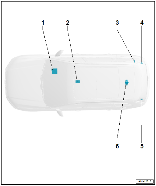
1 - Information Electronics Control Module 1 -J794-
2 - Not Installed
3 - Not Installed
4 - Right Bumper Antenna
- LTE Antenna 2 -R306-, ER3
5 - Left Bumper Antenna
- LTE Antenna 1 -R297-, ER1/ER2/ER3
6 - Roof Antenna -R216-
- LTE Antenna 2 -R306-, ER1/ER2
Antenna, removing and installing. Refer to → Chapter "Component Location Overview - Antenna Systems".
Fault finding is performed using the "Guided Fault Finding" on the Vehicle Diagnostic Tester.
Repairing antenna wires. Refer to → Chapter "General Repair Information".
Notes on Bluetooth Technology
A standardized radio connection is used for data transfer between the Information Electronics Control Module 1 -J794- and Cellular Telephone -R54- - Bluetooth technology. The range of the radio connection is approximately 10 m (11 yards).
Notes on MOST Bus
The optical data bus "MOST Bus" is used in addition to the CAN Bus.
A fiber-optic cable is used. Fiber optic cables are routed inside corrugated tubes for protection.
Replace the complete fiber-optic cable if possible.
The front surface of the connectors must not be contaminated.
If disconnecting the connectors: Attach the Fiber-Optic Repair Set - Connector Protective Caps -VAS6223/9-.
When routing fiber-optic cables, make sure not to go below the minimum bending radius of 25 mm. Do not crush or kink the fiber-optic cables.
Repairing fiber-optic cables. Refer to → Chapter "General Repair Information".
Overview - Telephone, Audi Phone Box, 9ZE
The Telephone Baseplate -R126- (phone box) is installed in the center console. The telephone is operated either by the infotainment system MMI or by the Cellular Telephone -R54-.
The microphones for the Microphone Unit In Front Roof Module -R164- are integrated in the Front Interior Lamp -W1-. One microphone (Left Front Microphone -R140-) is connected directly to the Information Electronics Control Module 1 -J794-. For IW3 with the Data Bus on Board Diagnostic Interface -J533-.
The Telephone Antenna -R65- in the Roof Antenna -R216- connects to the cellular network.
The antenna connection is located on the Cellular Telephone Amplifier -R86-.
9ZE - Audi Phone Box
1 - Telephone Antenna -R65- in the Roof Antenna -R216-
2 - Front Information Display Control Head -J685-, Display in Center of the Instrument Panel
3 - CAN Bus, MMI
4 - Multimedia System Control Head -E380- in the Center Console
5 - Information Electronics Control Module 1 -J794- in the Glove Compartment
6 - Sound Systems
7 - Left Front Microphone -R140-, Microphone Unit in Front Roof Module -R164- in the Front Interior Lamp -W1-
8 - Telephone Baseplate -R126- with Cellular Telephone -R54- in the Center Console Storage Compartment.
9 - Cellular Telephone Amplifier -R86- in Luggage Compartment on Right Rear Side
Antennas
9ZE/EL0 - phone box without connect:
- The Telephone Antenna -R65- is installed in the Roof Antenna -R216-
- No LTE antennas (-R297-/-R306-) are installed
Overview - Telephone Antennas
1 - Information Electronics Control Module 1 -J794-
2 - Telephone Baseplate -R126-
3 - Cellular Telephone Amplifier -R86-
4 - Not Installed
5 - Not Installed
6 - Roof Antenna -R216-
- Telephone Antenna -R65-
Antenna, removing and installing. Refer to → Chapter "Component Location Overview - Antenna Systems".
Fault finding is performed using the "Guided Fault Finding" on the Vehicle Diagnostic Tester.
Repairing antenna wires. Refer to → Chapter "General Repair Information".
Notes on Bluetooth technology
A standardized radio connection is used for data transfer between the Information Electronics Control Module 1 -J794- and Cellular Telephone -R54- - Bluetooth Technology.
The Information Electronics Control Module 1 -J794- is located in an additional transmitter/receiver with Bluetooth Antenna -R152-.
The range of the radio connection is approximately 10 m (11 yards).
Overview - Telephone, Audi Phone Box Connect, 9ZE/EL3
The Telephone Baseplate -R126- (phone box) is installed in the center console. The telephone is operated either by the Infotainment system MMI or by the Cellular Telephone -R54-.
The microphones for the Microphone Unit In Front Roof Module -R164- are integrated in the Front Interior Lamp -W1-. One microphone (Left Front Microphone -R140-) is connected directly to the Information Electronics Control Module 1 -J794-. For IW3 with the Data Bus on Board Diagnostic Interface -J533-.
The connection to the cellular network takes place via the Telephone Antenna -R65-.
The antenna connection is located on the Cellular Telephone Amplifier -R86-.
For the data transfer two LTE antennas are installed (LTE Antenna 1 -R297-/LTE Antenna 2 -R306-) and connected with the Information Electronics Control Module 1 -J794-.
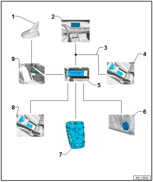
9ZE/EL3 - Audi Phone Box Connect
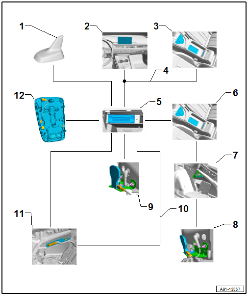
- Telephone Antenna -R65- in the Roof Antenna -R216-, ER3
2 - Front Information Display Control Head -J685-, Display in Center of the Instrument Panel
3 - Multimedia System Control Head -E380- in the Center Console
4 - CAN Bus, MMI
5 - Information Electronics Control Module 1 -J794- in the Glove Compartment
6 - Telephone Baseplate -R126- with Cellular Telephone -R54-
7 - Cellular Telephone Amplifier -R86- in Luggage Compartment on Right Rear Side
8 - Telephone Antenna -R65- on the Right Bumper, ER1/ER2
- LTE Antenna 2 -R306- on the Right Bumper, ER3
9 - LTE Antenna 1 -R297- on Left Bumper, ER1/ER2/ER3
10 - MOST Bus
11 - Digital Sound System Control Module -J525- in Luggage Compartment on Left Rear Side
12 - Left Front Microphone -R140-, Microphone Unit in Front Roof Module -R164- in the Front Interior Lamp -W1-
Antennas
9ZE/EL3 - phone box connect:
- USA (ER3): the Telephone Antenna -R65- is installed in the Roof Antenna -R216-
- USA (ER3): the LTE Antenna 2 -R306- is installed under the right rear bumper cover
- The LTE Antenna 1 -R297- is installed under the left rear bumper cover.
- Europe and Rest of World (ER1/ER2): the Telephone Antenna -R65- is installed under the right rear bumper cover
- Europe and Rest of World (ER1/ER2): the LTE Antenna 2 -R306- is installed in the Roof Antenna -R216-
Overview on Connect
1 - Information Electronics Control Module 1 -J794-
2 - Telephone Baseplate -R126-
3 - Cellular Telephone Amplifier -R86-
4 - Right Bumper Antenna
- Telephone Antenna -R65-, ER1/ER2
- LTE Antenna 2 -R306-, ER3
5 - Left Bumper Antenna
- LTE Antenna 1 -R297-, ER1/ER2/ER3
6 - Roof Antenna -R216-
- Telephone Antenna -R65-, ER3
- LTE Antenna 2 -R306-, ER1/ER2
Antenna, removing and installing. Refer to → Chapter "Component Location Overview - Antenna Systems".
Fault Finding is performed using the "Guided Fault Finding" on the Vehicle Diagnostic Tester.
Repairing Antenna Wires. Refer to → Chapter "General Repair Information".
Notes on Bluetooth Technology
A standardized radio connection is used for data transfer between the Information Electronics Control Module 1 -J794- and Cellular Telephone -R54- - Bluetooth Technology.
The Information Electronics Control Module 1 -J794- is located in an additional transmitter/receiver with Bluetooth Antenna -R152-.
The range of the radio connection is approximately 10 m (11 yards).
READ NEXT:
 Component Location Overview - Telephone System
1 - Center Console Storage Compartment
Removing and installing. Refer to
→ Body Interior; Rep. Gr.68; Center Console; Overview - Center Console.
2 - Telephone
Microphone Unit in Front Roof Module -R164-, Removing and Installing
The Microphone Unit in Front Roof Module -R164- in the Front
Interior Lamp -W1- is comprised of the Interior Microphone
-R74-, the Left Front Microphone -R140- and the Right Front
Microphone -R141-
SEE MORE:
Bulkhead
Overview - Bulkhead
1 -
Lock Washer
2 -
Heat Shield
Overview. Refer to
→ Chapter "Overview - Heat Shield".
3 -
Pass-Through
For coolant lines
Can be replaced only with the heat shield
Equipped on some models
4 -
Seal
For the plenum chamber bu
Hinge, Resetting
To complete the procedure, a second technician is required to be at the
following position.
NOTICE
Risk of damaging the hood by opening when the pedestrian
protection is triggered.
- Only open the hood after the triggered pedestrian
protection has been reset.
- Use tape to pr
