Audi A4: Component Location Overview - Telephone System
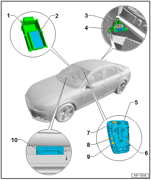
1 - Center Console Storage Compartment
- Removing and installing. Refer to → Body Interior; Rep. Gr.68; Center Console; Overview - Center Console.
2 - Telephone Baseplate -R126-
- Removing and installing. Refer to → Chapter "Telephone Baseplate -R126-, Removing and Installing".
3 - Bracket
- Nut tightening specification: 3 Nm
4 - Cellular Telephone Amplifier -R86-
- Connector assignment. Refer to → Wiring diagrams, Troubleshooting & Component locations.
- Removing and installing. Refer to → Chapter "Cellular Telephone Amplifier -R86-, Removing and Installing".
5 - Front Interior Lamp -W1-
- Removing and installing. Refer to → Electrical Equipment; Rep. Gr.96; Controls; Front Interior/Reading Lamp, Removing and Installing.
6 - Right Front Microphone -R141-
- 4-Pin Connector -T4-, black
- Removing and installing. Refer to → Chapter "Microphone Unit in Front Roof Module -R164-, Removing and Installing".
7 - 4-Pin Connector -T4dc-, Black
8 - Interior Microphone -R74-
- Removing and installing. Refer to → Chapter "Microphone Unit in Front Roof Module -R164-, Removing and Installing".
9 - Left Front Microphone -R140-
- 4-Pin Connector -T4-, red
- Removing and installing. Refer to → Chapter "Microphone Unit in Front Roof Module -R164-, Removing and Installing".
10 - Information Electronics Control Module 1 -J794-
- Connector assignment. Refer to → Wiring diagrams, Troubleshooting & Component locations.
- Removing and installing. Refer to → Chapter "Information Electronics Control Module 1 -J794-, Removing and Installing".
Overview - Microphone Unit
One microphone (Interior Microphone -R74-) is connected directly to the Digital Sound System Control Module -J525-. The other microphones are connected to the Information Electronics Control Module 1 -J794-.
For IW3 the Left Front Microphone -R140- is connected with the Data Bus on Board Diagnostic Interface -J533- and for 9ZE are "looped through" on the Information Electronics Control Module 1 -J794-.
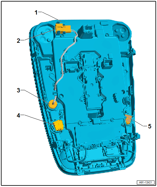
1 - Front Interior Lamp -W1-
- Removing and installing. Refer to → Electrical Equipment; Rep. Gr.96; Controls; Front Interior/Reading Lamp, Removing and Installing.
2 - 4-Pin Connector -T4dc-, Black
3 - Interior Microphone -R74-
- Removing and installing. Refer to → Chapter "Microphone Unit in Front Roof Module -R164-, Removing and Installing".
4 - Right Front Microphone -R141-
- 4-Pin Connector -T4-, black
- Removing and installing. Refer to → Chapter "Microphone Unit in Front Roof Module -R164-, Removing and Installing".
5 - Left Front Microphone -R140-
- 4-Pin Connector -T4-, red
- Removing and installing. Refer to → Chapter "Microphone Unit in Front Roof Module -R164-, Removing and Installing".
Microphone Unit in Front Roof Module -R164-, removing and installing. Refer to → Chapter "Microphone Unit in Front Roof Module -R164-, Removing and Installing".
READ NEXT:
 Microphone Unit in Front Roof Module -R164-, Removing and Installing
The Microphone Unit in Front Roof Module -R164- in the Front
Interior Lamp -W1- is comprised of the Interior Microphone
-R74-, the Left Front Microphone -R140- and the Right Front
Microphone -R141-
Overview - Navigation System
Overview - Navigation System, MMI Navigation, 7UF
7UF - Navigation
Information Electronics Control Module 1 -J794- with
integrated CD player/SD memory card reader/navigation system in
the glove comp
SEE MORE:
Special Tools
Special tools and workshop equipment required
Used Oil Collection and Extraction Unit -SMN372500-
Locking Pin -T10492-
Retaining Strap -T40155-
Oil Sump Assembly Pin -T40199-
Gearbox Support -T40206- and Gearbox Support - Drilling
Template -T40206/3-
Gearbox Assembly Tool -T40
Special Tools
Special tools and workshop equipment required
Seal Installer - Final Drive/Gearbox -T10337-
Puller - Crankshaft/Power Steering Seal -T20143/1-
Seal Installer - Flange Shaft -T40163-
Seal Installer - Output Shaft -T40239-
Circlip Pliers -VAS5503A-
Used Oil Collection and Extraction Unit -SM
