Audi A4: Overview - Navigation System
Overview - Navigation System, MMI Navigation, 7UF
7UF - Navigation
Information Electronics Control Module 1 -J794- with integrated CD player/SD memory card reader/navigation system in the glove compartment
- SD card with navigation data
- Front Information Display Control Head -J685-, display in center of the instrument panel
- Multimedia System Control Head -E380- in the center console, UJ0
- External Audio Source Connection -R199- (USB Charging, AUX IN) in the center console storage compartment, UE4
- Digital Sound System Control Module -J525- in the left rear of the luggage compartment, only 9VS
- Sound system: Standard/Bang & Olufsen, 9VD/9VS
- Radio -R- integrated in the Information Electronics Control Module 1 -J794-, I8S
- Bluetooth hands-free calling, 9ZX
- Voice recognition system, QH1
Optional
- Digital Radio -R147- integrated in the Information Electronics Control Module 1 -J794-, only ER1/ER2 and QV3
- Radio System, Satellite -R146- integrated in the Information Electronics Control Module 1 -J794-, only ER3 and QV3
- Instrument Cluster Control Module -J285-, instrument cluster display, 9S7
- External Audio Source Connection -R199- (USB quantity 2, Aux IN) in the center console storage compartment, UI2/UE7
- Audi phone box, 9ZE
- Audi phone box connect, 9ZE/EL3
- Multifunction Steering Wheel
ASI - Audi Smartphone Integration
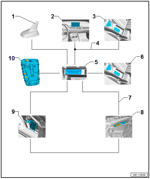
1 - GPS Antenna -R50- in the Roof Antenna -R216-
2 - Front Information Display Control Head -J685- Display in Center of the Instrument Panel
3 - Multimedia System Control Head -E380- in the Center Console
4 - Information Electronics Control Module 1 -J794- in the Glove Compartment
5 - Telephone Baseplate -R126-/External Audio Source Connection -R199- in the Center Console Storage Compartment
6 - MOST Bus
7 - Digital Sound System Control Module -J525- in Luggage Compartment on Left Rear Side
8 - TV Tuner -R78- in Luggage Compartment on Rear Right Side
9 - Microphone Unit in Front Roof Module -R164- in the Front Interior Lamp -W1-
Fault finding is performed using the "Guided Fault Finding" on the Vehicle Diagnostic Tester.
Repairing antenna wires. Refer to → Chapter "General Repair Information".
Notes on MOST Bus
The optical data bus "MOST Bus" is used in addition to the CAN Bus.
A fiber-optic cable is used. Fiber optic cables are routed inside corrugated tubes for protection.
Replace the complete fiber-optic cable if possible.
The front surface of the connectors must not be contaminated.
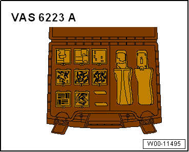
If disconnecting the connectors: Attach the Fiber-Optic Repair Set - Connector Protective Caps -VAS6223/9-.
When routing fiber-optic cables, make sure not to go below the minimum bending radius of 25 mm. Do not crush or kink the fiber-optic cables.
Repairing fiber-optic cables. Refer to → Chapter "General Repair Information".
Overview - Navigation System, MMI Navigation Plus, 7UG
7UG - Navigation Plus
Information Electronics Control Module 1 -J794- with integrated DVD player/SD memory card reader/navigation system/HDD in the glove compartment
- Internal hard drive memory (HDD) for storing navigation data and MP3 files
- Front Information Display Control Head -J685-, display in center of the instrument panel
- Multimedia System Control Head -E380- MMI touch in the center console, UJ1
- Instrument Cluster Control Module -J285-, instrument cluster display, 9S7
- External Audio Source Connection -R199- (USB Charging, AUX IN) in the center console storage compartment, UE4
- Digital Sound System Control Module -J525- in the left rear of the luggage compartment, only 9VS
- Sound system: Standard/Bang & Olufsen, 9VD/9VS
- Radio -R- integrated in the Information Electronics Control Module 1 -J794-, I8H
- Bluetooth hands-free calling, 9ZX
- Voice recognition system, QH1
Optional
- Digital Radio -R147- integrated in the Information Electronics Control Module 1 -J794-, only ER1/ER2 and QV3
- Radio System, Satellite -R146- integrated in the Information Electronics Control Module 1 -J794-, only ER3 and QV3
- TV Tuner -R78- in the right rear of the luggage compartment, QU1/QV1
- Instrument Cluster Control Module -J285-, instrument cluster display, 9S8
- External Audio Source Connection -R199- (USB quantity 2, Aux IN) in the center console storage compartment, UI2/UE7
- Audi phone box, 9ZE
- Audi phone box connect, 9ZE/EL3
- Multifunction Steering Wheel
ASI - Audi Smartphone Integration
1 - GPS Antenna -R50- in the Roof Antenna -R216-
2 - Front Information Display Control Head -J685- Display in Center of the Instrument Panel
3 - Multimedia System Control Head -E380- in the Center Console
4 - Information Electronics Control Module 1 -J794- in the Glove Compartment
5 - Telephone Baseplate -R126-/External Audio Source Connection -R199- in the Center Console Storage Compartment
6 - MOST Bus
7 - Digital Sound System Control Module -J525- in Luggage Compartment on Left Rear Side
8 - TV Tuner -R78- in Luggage Compartment on Rear Right Side
9 - Microphone Unit in Front Roof Module -R164- in the Front Interior Lamp -W1-
Fault finding is performed using the "Guided Fault Finding" on the Vehicle Diagnostic Tester.
Repairing antenna wires. Refer to → Chapter "General Repair Information".
Notes on MOST Bus
The optical data bus "MOST Bus" is used in addition to the CAN Bus.
A fiber-optic cable is used. Fiber optic cables are routed inside corrugated tubes for protection.
Replace the complete fiber-optic cable if possible.
The front surface of the connectors must not be contaminated.
If disconnecting the connectors: Attach the Fiber-Optic Repair Set - Connector Protective Caps -VAS6223/9-.
When routing fiber-optic cables, make sure not to go below the minimum bending radius of 25 mm. Do not crush or kink the fiber-optic cables.
Repairing fiber-optic cables. Refer to → Chapter "General Repair Information".
READ NEXT:
 Component Location Overview - Navigation System
1 - Bracket
2 - Bolt
3 Nm
Quantity: 2
3 - Information Electronics Control Module 1 -J794-
Connector assignment. Refer to
→ Wiring diagrams, Troublesho
Overview - Rearview Camera System
The rear view camera system (KA2) assists the driver during
back-up driving for diagonal and parallel parking for trailer
towing and watching cross traffic by providing the driver with
an image of
SEE MORE:
Audi active lane assist/lane departure warning
General information
Applies to: vehicles with Audi active lane assist
The Audi active lane assist/lane departure warning
(called only Audi active lane assist in the vehicle
displays and in the information that follows in
this Owner's Manual) can detect lane marker
lines within the limits of the syst
General Information
High pressure side are the condenser, receiver/dryer and
restrictor or expansion valve to separate the high and low
pressure liquid ends.
High pressure results from the restrictor or expansion valve
forming a constriction and causing the refrigerant to
accumulate, thus leading to an increase in
