Audi A4: Component Location Overview - Navigation System
Audi A4 (B9) 2016-2026 Service Manual / Electrical System / Communication / Navigation System / Component Location Overview - Navigation System
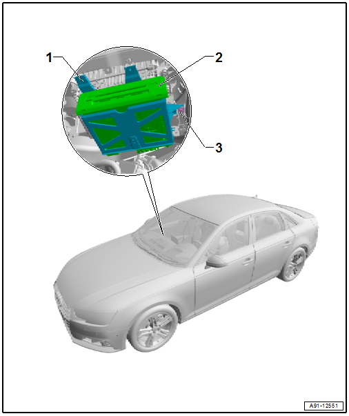
1 - Bracket
2 - Bolt
- 3 Nm
- Quantity: 2
3 - Information Electronics Control Module 1 -J794-
- Connector assignment. Refer to → Wiring diagrams, Troubleshooting & Component locations.
- Removing and installing. Refer to → Chapter "Information Electronics Control Module 1 -J794-, Removing and Installing".
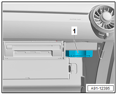
Chip Card Reader Control Module, Removing and Installing
The Chip Card Reader Control Module -J676- is located in the glove compartment (only ER5).
Removing
- Turn off the ignition and all electrical equipment and remove the ignition key.
- Open the glove compartment.
- Remove the chip card.
- Slide the Chip Card Reader Control Module -J676--1- back until it can be removed from the trim.
- Release and disconnect the connectors from the Chip Card Reader Control Module -J676--1-.
Installing
- Install in reverse order of removal. Note the following:
- Make sure that all of the retaining tabs on the Chip Card Reader Control Module -J676--1- engage into the trim.
READ NEXT:
 Overview - Rearview Camera System
The rear view camera system (KA2) assists the driver during
back-up driving for diagonal and parallel parking for trailer
towing and watching cross traffic by providing the driver with
an image of
Rearview Camera -R189-, Removing and Installing
Rearview Camera -R189-, Removing and Installing, Sedan
The Rearview Camera -R189- is inside the rear lid handle
button. It permanently attached to the handle button.
If the Rearview Camera -R189- mus
SEE MORE:
Software update
Introduction
Applies to: vehicles with software update
You can update your vehicle's software.
The functions depend on the country and vehicle
equipment:
Update through the online system update
Map material update for the navigation system
Have the software update performed by an authorized
Aud
Speed warning system
Description
Applies to: vehicles with speed warning system
The speed warning system helps the driver to
stay below a specified maximum speed. A warning
threshold can be set in the MMI for this purpose.
Once the speed slightly exceeds the stored
threshold, the speed warning system will alert
the d
© 2019-2026 Copyright www.audia4b9.com
