Audi A4: Rearview Camera -R189-, Removing and Installing
Rearview Camera -R189-, Removing and Installing, Sedan
The Rearview Camera -R189- is inside the rear lid handle button. It permanently attached to the handle button.
If the Rearview Camera -R189- must be replaced, then the handle button must also be replaced.
Removing
- Turn off the ignition and all electrical equipment and remove the ignition key.
The Rearview Camera -R189- has a trailing cable. The vehicle wiring harness couplings are located in the rear lid.
- Remove the rear lid lower trim panel. Refer to → Body Interior; Rep. Gr.70; Luggage Compartment Trim Panels; Overview - Lower Rear Lid Trim Panel.
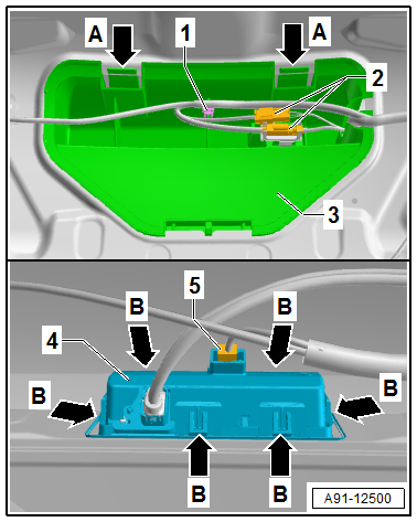
- Release and disconnect the connectors -2-.
- Remove the cable bracket -1- from the anti-theft protection -3-.
- Release the retainers -A arrows-.
- Remove the anti-theft protection -3- from the rear lid.
- Release and disconnect the connector -5-.
- Release the catches -B arrows-.
- Remove the handle button -4- from the rear lid.
Installing
- Install in reverse order of removal. Note the following:
- Close the rear lid.
- Perform the calibration. Refer to → Chapter "Rearview Camera System, Calibrating".
Rearview Camera -R189-, Removing and Installing, Avant
The Rearview Camera -R189- is inside the rear lid handle button. It permanently attached to the handle button.
If the Rearview Camera -R189- must be replaced, then the handle button must also be replaced.
Removing
- Turn off the ignition and all electrical equipment and remove the ignition key.
The Rearview Camera -R189- has a trailing cable. The vehicle wiring harness couplings are located in the rear lid.
- Remove the rear lid lower trim panel. Refer to → Body Interior; Rep. Gr.70; Luggage Compartment Trim Panels; Overview - Lower Rear Lid Trim Panel.
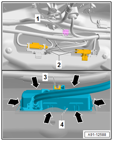
- Release and disconnect the connectors -2-.
- Remove the cable bracket -1- from the rear lid.
- Release and disconnect the connector -3-.
- Release the retainers -arrows-.
- Remove the handle button -4- from the rear lid.
Installing
- Install in reverse order of removal. Note the following:
- Close the rear lid.
- Perform the calibration. Refer to → Chapter "Rearview Camera System, Calibrating".
Rearview Camera System Control Module -J772-, Removing and Installing
The Rearview Camera System Control Module -J772- is located in the Rearview Camera -R189- and cannot be replaced separately.
 Note
Note
If replacing the control module, select the "Replace control module" function for the corresponding control module on the Vehicle Diagnostic Tester.
Removing
- Turn off the ignition and all electrical equipment and remove the ignition key.
- Remove the Rearview Camera -R189-. Refer to → Chapter "Rearview Camera -R189-, Removing and Installing".
Installing
- Install the Rearview Camera -R189-. Refer to → Chapter "Rearview Camera -R189-, Removing and Installing".
- Perform the calibration. Refer to → Chapter "Rearview Camera System, Calibrating".
READ NEXT:
 Rearview Camera System, Calibrating
Calibration Unit -VAS6350A-, Installing and Aligning
After performing repair work on the vehicle, it may be
necessary to re-calibrate the rearview camera system. In detail,
this is the case after:
General Information - Multifunction Steering Wheel
The button is integrated in the steering wheel for easier
operation of infotainment, telephone and the navigation system.
On Tiptronic, rocker switches are also installed on the left and
right.
The
SEE MORE:
Airbag Adapter, Connecting and Disconnecting
Special tools and workshop equipment required
Airbag Lockout Adapter -VAS6282-
Airbag Connector, Disconnecting
- Move the front seat all the way to the rear and then into its
highest position.
- Fold up the cover in the carpet.
WARNING
Risk of injury due to involuntary deploy
Sliding Sunroof
Overview - Sliding Sunroof
Overview - Sliding Sunroof, Sedan
1 -
Screw
3 Nm
Quantity: 2
2 -
Sunroof Motor -V1-
Removing and installing. Refer to
→ Chapter "Sunroof Motor -V1-, Removing and Installing".
Perform the adaptation after installing. Refer to
→ Chap
