Audi A4: Rearview Camera System, Calibrating
Calibration Unit -VAS6350A-, Installing and Aligning
After performing repair work on the vehicle, it may be necessary to re-calibrate the rearview camera system. In detail, this is the case after:
- Rearview Camera -R189- removal and installation
- Collision repairs on rear lid
- Changes to the axle alignment on the rear axle
Calibration Requirements
- The camera lens must be clean.
- The vehicle must be standing on a firm and level surface.
- There must be sufficient open space around the vehicle.
- The parking brake must be set.
- The steering wheel must be in the 0 position and the wheels must be straight.
- All doors and the rear lid must be closed.
- No one should be in the vehicle.
- The vehicle must not be loaded (curb weight).
- Before each calibration: turn on the ignition.
Special tools and workshop equipment required
- Calibration Unit -VAS6350A-
- Vehicle Diagnostic Tester
The Calibration Unit -VAS6350A- consists of the following parts:
- Calibration Tool - Wheel Center Mountings -VAS6350/1-
- Calibration Tool - Spacing Laser -VAS6350/2-
- Calibration Tool - Linear Laser -VAS6350/3-
Installed Calibration Unit -VAS6350A- Overview
 Note
Note
The vehicle in the illustration is only a basic outline.
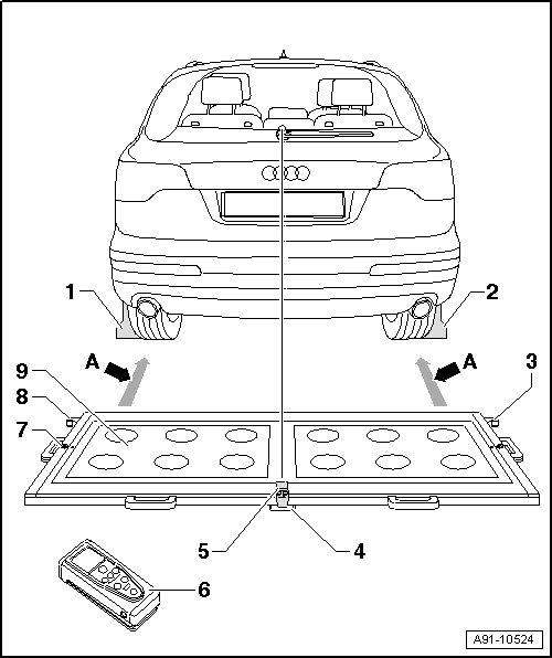
1 - Calibration Tool - Wheel Center Mountings -VAS6350/1-
2 - Calibration Tool - Wheel Center Mountings -VAS6350/1-
3 - Right Angle Bracket
- Calibration Tool - Spacing Laser -VAS6350/2- mount
4 - Plastic Foot
- Three on underside of the calibration board
- Adjustable for aligning horizontal position of the calibration board
5 - Calibration Tool - Linear Laser -VAS6350/3-
- On the calibration board
- Switching on and off. Refer to the Owner's Manual.
6 - Calibration Tool - Spacing Laser -VAS6350/2-
- On the calibration board
- Refer to the Owner's Manual for notes on the operation.
7 - Level
- On the calibration board
- For checking the horizontal position
8 - Left Angle Bracket
- Calibration Tool - Spacing Laser -VAS6350/2- mount
9 - Calibration Board
- Between the mounts on the calibration board and the Calibration Tool - Wheel Center Mountings -VAS6350/1--dimension A- 1.4 to 1.9 meters (1.5 to 2 yards)
Calibration Board Orientation
- Position the calibration platform behind the vehicle at a distance of 1.4 to 1.9 meters (1.5 to 2 yards) to the rear wheels, see -dimension A- in the overview illustration.
- Bring the Calibration Unit -VAS6350A- into a horizontal position.
- Twist the plastic feet under the calibration board so that the air bubble in the level is located exactly in the center of the indicator -arrow-.
 WARNING
Make sure light does not reflect off the calibration board.
Reflections impair the Rearview Camera -R189- and may make it impossible to perform the calibration.
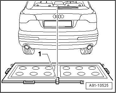
Note
The vehicle in the illustration is only a basic outline.
- Switch on the Calibration Tool - Linear Laser -VAS6350/3--1- on the calibration board and adjust the entire Calibration Unit -VAS6350A- so that the laser beam hits the center of vehicle rear above the Audi rings.
- Check that the Audi rings are centered on the rear. Correct the laser beam accordingly.
Continue calibrating the Rearview Camera -R189-. Refer to → Chapter "Rearview Camera -R189-, Calibrating".
Rearview Camera -R189-, Calibrating
- Establish the requirements.
- Connect the Vehicle Diagnostic Tester.
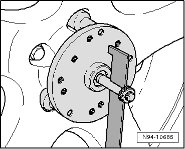
Calibration Tool - Wheel Center Mountings -VAS6350/1- Installing
- Check which hole circle the rims have.
- Equip the Calibration Tool - Wheel Center Mountings -VAS6350/1- appropriately.
- To do so, secure the three wheel bolt adapters in the hole circle to each Calibration Tool - Wheel Center Mountings -VAS6350/1-.
- Place the paddle on both Calibration Tool - Wheel Center Mountings -VAS6350/1- and secure them using a clamping screw.
- Place the Calibration Tool - Wheel Center Mountings -VAS6350/1- onto the wheel bolts on the rear wheels.
The Calibration Tool - Wheel Center Mountings -VAS6350/1- are positioned by the "O-rings" in the adapters and secured.
Note
Attach the Calibration Tool - Wheel Center Mountings -VAS6350/1- onto the wheels so that any installed "anti-theft" wheel bolts are not connected to the Calibration Tool - Wheel Center Mountings -VAS6350/1-.
- Adjust the paddles with the aid of clamping screw so that they move freely just above the floor. Check the paddles for ease of movement.
- Install and align the Calibration Unit -VAS6350A-. Refer to → Chapter "Calibration Unit -VAS6350A-, Installing and Aligning".
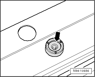
Distance Measurement
- Switch on the Calibration Tool - Spacing Laser -VAS6350/2-.
The following display appears.
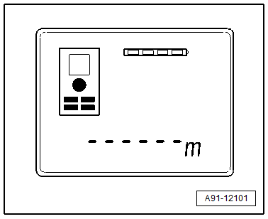
The display shows how to stop the Calibration Tool - Spacing Laser -VAS6350/2-. Press the corresponding button.
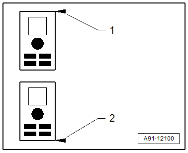
1 - Attach with front edge
2 - Attach with rear edge
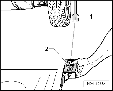
- Hold the Calibration Tool - Spacing Laser -VAS6350/2--2- flush in the bracket on one side of the calibration board as shown. The Calibration Tool - Spacing Laser -VAS6350/2--2- must sit securely on the bracket at the same time.
- Push the measurement button briefly.
The laser switches on.
The laser beam from the Calibration Tool - Spacing Laser -VAS6350/2--2- must hit the lower, enlarged section of the paddle -1-.
If this is not the case, the paddles must be corrected accordingly via clamping screws on the Calibration Tool - Wheel Center Mountings -VAS6350/1-.
- Use one hand to secure the Calibration Tool - Spacing Laser -VAS6350/2- in the bracket on the Calibration Tool -VAS6350- while the laser beam is visible on the paddle.
- Then press the measurement button for the distance measurement briefly.
- Write down the value.
- Repeat this measurement on the other side of the Calibration Tool -VAS6350- in the same way for the rear wheel.
The distance value must be the same on both sides.
If values are not identical:
- Align the Calibration Unit -VAS6350A- long enough so that both sides are identical.
- When adjusting, make sure the Calibration Tool - Linear Laser -VAS6350/3A- strikes the center above the Audi rings and that the level indicator remains centered. Adjust if necessary.
Dimension Measurement -H-
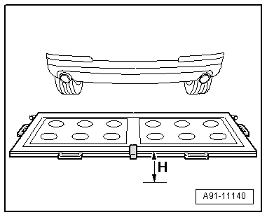
- Measure the height of the Calibration Unit -VAS6350A-, dimension -H- (top edge platform - floor).
Make sure the Calibration Tool - Spacing Laser -VAS6350/2- is adjusted correctly (attach with front edge).
The display shows how to stop the Calibration Tool - Spacing Laser -VAS6350/2-. Press the corresponding button.
1 - Attach with front edge
2 - Attach with rear edge
- Then with a commercially available folding ruler measure the height of the camera lens center of the rearview camera to the wheel contact surface.
- Mark the determined height.
The measured distance measurement, the height of the calibration device and the height of the center of the rearview camera lens must be entered in the Vehicle Diagnostic Tester in "mm".
Calibrating Procedure
The Vehicle Diagnostic Tester is connected.
- Select the Diagnostic mode and start the diagnosis.
- Select the Test plan tab.
- Press the Select individual test button and select the following one after the other:
- Body
- Electrical Equipment
- 01 - OBD-capable systems
- 6C - Rearview camera system control module - J772
- 6C - Rearview camera system control module, functions
- 6C - Calibrating
From here, the Vehicle Diagnostic Tester advances the calibration procedure forward.
WARNING
Make sure light does not reflect off the calibration board.
Reflections impair the Rearview Camera -R189- and may make it impossible to perform the calibration.
READ NEXT:
 General Information - Multifunction Steering Wheel
The button is integrated in the steering wheel for easier
operation of infotainment, telephone and the navigation system.
On Tiptronic, rocker switches are also installed on the left and
right.
The
Right and Left Multifunction Buttons on Steering Wheel -E441-/-E440-,
Removing and Installing
Right and Left Multifunction Buttons on Steering Wheel -E441-/-E440-,
Removing and Installing, Steering Wheel with Round Airbag
Special tools and workshop equipment required
Trim Removal Wedge -340
SEE MORE:
Overview - Subframe
Overview - Subframe, FWD
Caution
There is a risk of damaging the threads on the subframe
threaded connection to the body.
The subframe bolts on the body must not be loosened or
tightened with an impact wrench.
Always install all bolts by hand for the first few turns.
1 - Bo
Roof Molding/Roof Railing
Overview - Roof Railing
1 -
Nut
Quantity: 4
Insert with locking fluid. Refer to the Parts Catalog.
Tightening specification and sequence. Refer to
→ Fig. "Roof Railing - Tightening Specification and Sequence".
2 -
O-Ring
Replace if damaged
3 -
Lifter
0.5
