Audi A4: Dual Clutch, Removing and Installing
Special tools and workshop equipment required
- Shop Crane -VAS6100-
- Puller - Input Shaft -T40050-
- Pressure Stand -T40099-
- Guide Pins - Gearbox -T40288-
- Engine Support Bridge - Additional Hooks (2 pc.) -10-222A/2-
Removing
- Secure the transmission on the Engine And Transmission Holder -VAS6095-. Refer to → Chapter "Securing on Engine and Transmission Holder".
- Remove the flywheel. Refer to → Chapter "Flywheel, Removing and Installing".
- Turn the transmission in the Engine and Gearbox Bracket -VAS6095A- so that it is vertical.
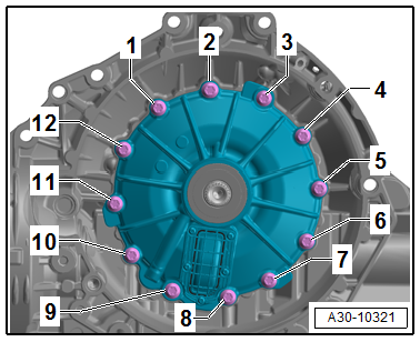
- Remove the bolts -1 to 12-.
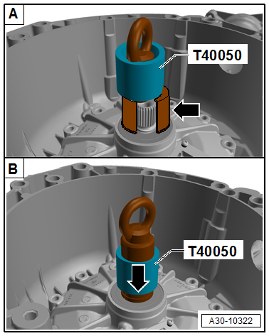
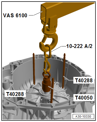
- Place the Puller - Input Shaft -T40050- on the input shaft clutch and lock -arrows-.
- Make sure the puller is secure on the input shaft.
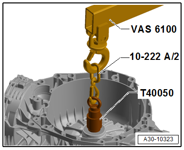
- Connect the Puller - Input Shaft -T40050- with the Engine Support Bridge - Additional Hooks (2 pc.) -10-222A/2- and engage in the Shop Crane -VAS6100-.
- Carefully remove the dual clutch out of the transmission housing.
 Caution
When removing, the engaging bearing and both alignment sleeves can fall out of the transmission housing.
A damaged or dropped engaging bearing must be replaced.
 Note
Note
- The dual clutch is extensively calibrated on the engaging bearing and slave cylinder.
- Calibrating with service equipment is not possible.
- A damaged engaging bearing or slave cylinder must for this reason always be replaced with a new clutch.
- A new clutch is always supplied with a calibrated engaging bearing and slave cylinder.
Caution
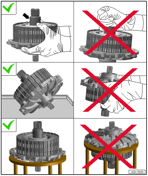
There is a risk of damaging the dual clutch from mishandling.
- The hub for "clutch 2" -arrow- is clipped in the inner disk support and can be loosed through mishandling of the clutch.
- Transport and position the clutch only as shown:
It can be checked by measuring the height dimension if the clutch is damaged.
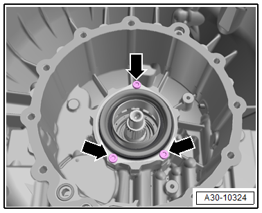
- Remove the three bolts -arrows- and remove the engaging bearing with the slave cylinder.
Note
Depending on the version the three bolts -arrows- may not be present.
Installing
Note
The double shaft seal for the input shaft must always be replaced! Refer to → Chapter "Input Shaft Double Shaft Seal, Replacing".
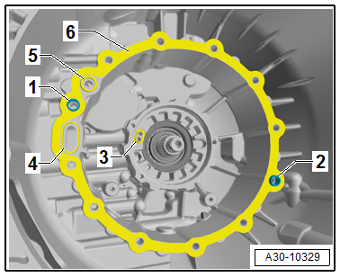
- Check if the sleeves -1 and 2- are installed.
- Coat the new seals -3, 4 and 5- with ATF and install.
- Insert the seal -6-.
Note
Make sure no dirt can fall into the transmission while cleaning.
- Install the engaging bearing with the slave cylinder and tighten the three bolts -arrows- evenly.
Note
Depending on the version the three bolts -arrows- may not be present.
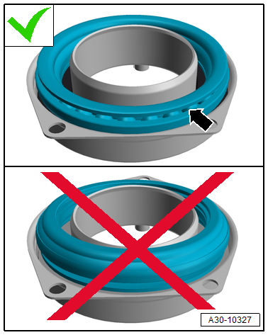
Note
- Pay attention that the engaging bearing is installed correctly to the slave cylinder.
- The ball bearings are visible! -Arrow-
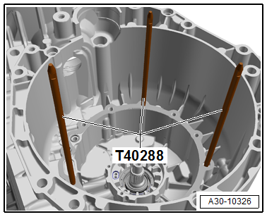
- Install the Guide Pins - Gearbox -T40288- in the threaded hole approximately 120º offset.
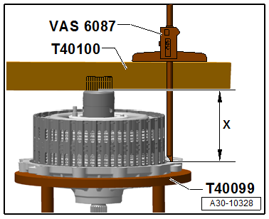
Check the Clutch Installation Height
- Before installing the clutch the dimension -x- must be determined.
- To do so use the Ruler (2 pc.) -T40100- and Digital Depth Gauge -VAS6087- to determine the height of the clutch cover to the hub offset as shown.
The dimension -x- must be located within the tolerance of 98.91 to 99.61 mm.
Note
If the dimension -x- is outside of the tolerance, the clutch must be replaced because it is damaged.
- Place the dual clutch as shown in the transmission housing.
- Tighten the bolts -1 to 12- for the clutch cover diagonally in steps. Tightening specification. Refer to → Chapter "Overview - Flywheel and Dual Clutch".
- Install the flywheel. Refer to → Chapter "Flywheel, Removing and Installing".
- After installing the transmission fill the ATF and transmission fluid. Refer to → Rep. Gr.34; ATF; ATF, Draining and Filling and → Rep. Gr.34; Transmission Fluid; Transmission Fluid, Draining and Filling
- After changing the dual clutch the clutch must be adapted. Refer to Vehicle Diagnostic Tester.
Procedure:
- Drivetrain
- 0CK Transmission
- 01 OBD-capable systems
- 02-Transmission electronics
- 02-Transmission electronics, functions
- 02-Basic Setting
- 04-Adapt clutch slip points
READ NEXT:
 Input Shaft Double Shaft Seal, Replacing
Special tools and workshop equipment required
Puller - Crankshaft/Power Steering Seal -T20143-
Thrust Piece -T40300-
Clutch, engaging bearing and slave cylinder removed. Refer
to
→ Chap
Transmission, Transporting
Special tools and workshop equipment required
Shop Crane -VAS6100-
Lifting Tackle -3033-
Hook And Support Tool -3311- with Hook And Support Tool -
Bolt -3311/1-
Retaining Strap -T40155-
SEE MORE:
Overview - Suspension Strut, Shock Absorber, Spring
Overview - Spring
1 - Rear Lower Transverse Link
Removing and installing. Refer to
→ Chapter "Rear Lower Transverse Link, Removing and Installing".
2 - Coil Spring
Removing and installing. Refer to
→ Chapter "Spring, Removing and Installing".
Installation p
Gearshift Mechanism, Checking
WARNING
Risk of injury and accident by accidentally engaging
a selector lever position with the engine running.
Before working with the engine running, move the
transmission into "P" and pull the parking brake button
to activate the electro-mechanical parking brake.
Pay attention to t
