Audi A4: Shock Absorber Fork, Removing and Installing
Special tools and workshop equipment required
- Spreader Tool -3424-
- Torque Wrench 1331 5-50Nm -VAG1331-
- Torque Wrench 1332 40-200Nm -VAG1332-
 Caution
This procedure contains mandatory replaceable parts. Refer to component overview and parts catalog prior to starting procedure.
Mandatory Replacement Parts
- Nut - Coupling Rod to Shock Absorber Fork
- Bolt - Control Arm to Shock Absorber Fork
Removing
- Before starting the procedure, determine the curb weight position. Refer to → Chapter "Wheel Bearing in Curb Weight Position, Lifting Vehicles with Coil Spring".
- Remove the front wheel. Refer to → Chapter "Wheels and Tires".
- Remove the coupling rod. Refer to → Chapter "Coupling Rod, Removing and Installing".
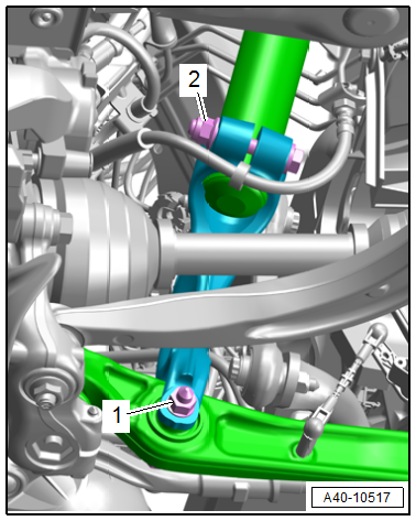
- Disconnect the connectors -1 and 2- for the shock absorber fork.
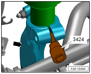
- Insert the -3424- into the slot in the shock absorber fork -arrow-.
Caution
There is a risk of damaging the ball joint.
The upper control arm ball joint must not be pushed past the maximum bending point.
- Remove the shock absorber fork downward from the shock absorber tube and remove, while pushing the wheel bearing housing carefully downward.
Installing
Install in reverse order of removal and note the following:
- Attach the shock absorber fork.
- Install the threaded connections for the components with bonded rubber bushings only until the stop, but do not tighten yet.
 Note
Note
Bonded rubber bushings have a limited range of rotation. Only tighten the threaded connections for the suspension when the vehicle is in curb weight position.
- Lift the wheel bearing in curb weight position. Refer to → Chapter "Wheel Bearing in Curb Weight Position, Lifting Vehicles with Coil Spring".
- Overview table for when an axle alignment is needed. Refer to → Chapter "Need for Axle Alignment, Evaluating".
Tightening Specifications
- Refer to → Chapter "Overview - Subframe"
- Refer to → Chapter "Overview - Suspension Strut and Upper Control Arm"
- Refer to → Chapter "Overview - Lower Control Arm and Ball Joint"
- Refer to → Chapter "Wheels and Tires"
Tower Brace, Removing and Installing
Special tools and workshop equipment required
- Torque Wrench 1331 5-50Nm -VAG1331-
Removing
- Remove the plenum chamber cover. Refer to → Body Exterior; Rep. Gr.50; Bulkhead; Plenum Chamber Cover, Removing and Installing.
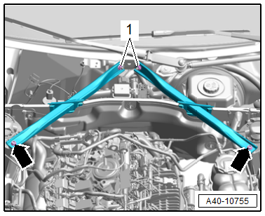
- Remove the nuts -1- and bolts -arrows-, and remove the tower brace.
Installing
Install in reverse order of removal.
Tightening Specifications
- Refer to → Chapter "Overview - Tower Brace"
READ NEXT:
 Overview - Lower Control Arm and Ball Joint
1 - Wheel Bearing Housing Side Bonded Rubber Bushing
Replacing. Refer to
→ Chapter "Control Arm Ball Bearing, Replacing, Wheel Bearing Housing
Side".
2 - Bolt
Replac
Control Arm, Removing and Installing
Special tools and workshop equipment required
Spreader Tool -3424-
Torque Wrench 1332 40-200Nm -VAG1332-
Engine and Gearbox Jack -VAS6931-
Ball Joint Splitter -VAS251805-
Engine/Gearbox Jack Ada
SEE MORE:
Transmission Fluid
Transmission Fluid Level, Checking
Special tools and workshop equipment required
Torx Socket - T60 -T40087-
Protective Eyewear
Procedure
Note
General repair instructions. Refer to
→ Chapter "Repair Information".
Guidelines for clean working conditions. Refer to
→ Chapte
Rear Seats
Overview - Bench Seat/Single Seat
1 - Grommets
For securing the rear bench seat
Clipped into the vehicle floor
Replace each time the bench seat is removed
2 - Bench Seat
Removing and installing. Refer to
→ Chapter "Bench Seat/Single Seat, Removing and Installing".
