Audi A4: Stabilizer Bar, Removing and Installing
Special tools and workshop equipment required
- Torque Wrench 1331 5-50Nm -VAG1331-
 Caution
This procedure contains mandatory replaceable parts. Refer to component overview and parts catalog prior to starting procedure.
Mandatory Replacement Parts
- Nut - Stabilizer Bar to Coupling Rod
Removing
- Before starting the procedure, determine the curb weight position. Refer to → Chapter "Wheel Bearing in Curb Weight Position, Lifting Vehicles with Coil Spring".
- Lower the subframe crossbrace and do not press off the guide link joint pin while doing this. Refer to → Chapter "Subframe Crossbrace, Removing and Installing".
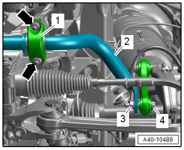
- Remove the left and right nuts -arrows and 3-.
- Remove the left and right clamp -1- and bolt -4-.
- Remove the stabilizer bar -2-.
Installing
Install in reverse order of removal and note the following:
 Note
Note
- There must be no grease on the stabilizer bar and rubber bushing.
- If a stud bolt for the clamp has loosened, tighten it all the way.
- Install the threaded connections for the stabilizer bar only until the stop, but do not tighten yet.
Note
Bonded rubber bushings have a limited range of rotation. Only tighten the threaded connections for the suspension when the vehicle is in curb weight position.
- Lift the wheel bearing in curb weight position. Refer to → Chapter "Wheel Bearing in Curb Weight Position, Lifting Vehicles with Coil Spring".
Tightening Specifications
- Refer to → Chapter "Overview - Subframe"
Coupling Rod, Removing and Installing
Special tools and workshop equipment required
- Torque Wrench 1332 40-200Nm -VAG1332-
Caution
This procedure contains mandatory replaceable parts. Refer to component overview and parts catalog prior to starting procedure.
Mandatory Replacement Parts
- Nut - Coupling Rod to Shock Absorber Fork
- Nut - Stabilizer Bar to Coupling Rod
Removing
- Before starting the procedure, determine the curb weight position. Refer to → Chapter "Wheel Bearing in Curb Weight Position, Lifting Vehicles with Coil Spring".
- Remove the front wheel spoiler. Refer to → Body Exterior; Rep. Gr.66; Wheel Housing Liner; Front Wheel Housing Liner, Removing and Installing.
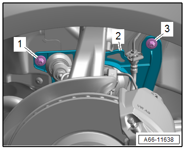
- Remove the nuts -1 and 3- and remove the drive axle cover -2-.
- Remove the nuts -arrows-.
- Remove the bolts -1 and 3- and coupling rod -2-.
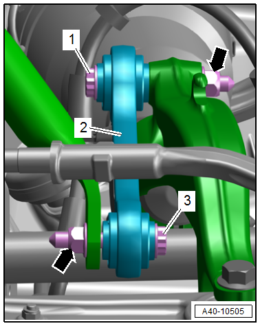
Note
Push the front wheels in accordingly if required to remove the lower bolt.
Installing
Install in reverse order of removal and note the following:
- Install the threaded connections for the components with bonded rubber bushings only until the stop, but do not tighten yet.
Note
Bonded rubber bushings have a limited range of rotation. Only tighten the threaded connections for the suspension when the vehicle is in curb weight position.
- Lift the wheel bearing in curb weight position. Refer to → Chapter "Wheel Bearing in Curb Weight Position, Lifting Vehicles with Coil Spring".
Tightening Specifications
- Refer to → Chapter "Overview - Subframe"
- Refer to → Body Exterior; Rep. Gr.66; Wheel Housing Liner; Overview - Front Wheel Housing Liner.
READ NEXT:
 Overview - Suspension Strut and Upper Control Arm
Overview - Suspension Strut and Upper Control Arm
1 - Bolt
Replace after removing
2 - Control Arm
3 - Shock Absorber Fork
Removing and installing. Refer to
→&nbs
Suspension Strut, Removing and Installing
Torque Wrench 1331 5-50Nm -VAG1331-
Removing
- Remove the shock absorber fork. Refer to
→ Chapter "Shock Absorber Fork, Removing and Installing".
- Remove the tower brace. Refer t
SEE MORE:
Expansion Valve
The expansion valve atomizes the streaming refrigerant and
controls the flow quantity so that the vapor is gaseous only at
the evaporator outlet, depending on the heat transmission.
Note
Be sure to use the correct part number when replacing the
expansion valve. Refer to the Parts Catalo
Electronic Stabilization
Control
Description
Electronic Stabilization Control (ESC) supports
driver safety. It reduces the risk of slipping and
improves driving stability. ESC detects critical situations,
such as if the vehicle is oversteering or
understeering, or if the wheels are spinning.
The brakes are applied or the motor t
