Audi A4: Instrument Panel Central Tube
Overview - Instrument Panel Central Tube
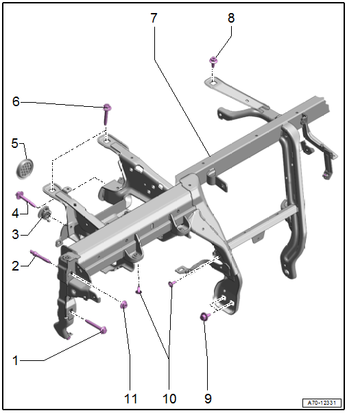
1 - Bolt
- 20 Nm
- Quantity: 2
- The mounting threads and contact surface must be free of paint, coating, and corrosion. The threaded connection serves as the ground connection
2 - Threaded Pin
- 20 Nm
- Quantity: 2
3 - Lifter
- Quantity: 2
- Clip in on the central tube
- Check the lifter adjusting nut for ease of movement
- Turn the adjusting nut all the way downward until the adjuster in the transportation safeguard engages
4 - Bolt
- 20 Nm
- Quantity: 2
5 - Plug
- Quantity: 2
6 - Bolt
- 20 Nm
- Quantity: 2
7 - Central Tube
- For the instrument panel
- Removing and installing. Refer to → Chapter "Instrument Panel Central Tube, Removing and Installing".
8 - Bolt
- 20 Nm
- 9 - Bolt
- 20 Nm
- Quantity: 3
10 - Bolt
- 3.6 Nm
- Quantity: 5
- For A/C unit
11 - Nut
- 20 Nm
- Replace after removing
- Quantity: 2
Instrument Panel Central Tube, Removing and Installing
Special tools and workshop equipment required
- Pry Lever -80-200-
 Caution
This procedure contains mandatory replaceable parts. Refer to component overview and parts catalog prior to starting procedure.
Mandatory Replacement Parts
- Nut - Central Tube to Threaded Pin
Removing
- Remove the windshield wiper motor. Refer to → Electrical Equipment; Rep. Gr.92; Windshield Wiper System; Windshield Wiper MotorV Removing and Installing.
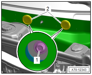
- Remove the plugs -2- and remove the bolt -1- for the central tube on the plenum chamber bulkhead.
- Remove the windshield. Refer to → Body Exterior; Rep. Gr.64; Windshield; Windshield, Removing and Installing.
- Remove the instrument panel. Refer to → Chapter "Instrument Panel, Removing and Installing".
- Equipped on some models: Remove the Windshield Projection Head Up Display Control Module -J898-. Refer to → Electrical Equipment; Rep. Gr.90; Instrument Cluster; Windshield Projection Head Up Display Control Module, Removing and Installing.
- Remove the air guide and air duct to the instrument panel vent from the instrument panel central tube. Refer to → Heating, Ventilation and Air Conditioning; Rep. Gr.87; Air Routing; Overview - Air Routing and Air Distribution in Vehicle Interior.
- Remove the air duct center piece to the center defroster vent. Refer to → Heating, Ventilation and Air Conditioning; Rep. Gr.87; Air Duct; Overview - Air Ducts and Air Distribution in Passenger Compartment.
- Remove the left A-pillar fuse panel from the instrument panel central tube. Refer to → Electrical Equipment; Rep. Gr.97; Relay Panels, Fuse Panels and E-Boxes; Component Location Overview - Relay Panels, Fuse Panels and E-Boxes.
- Remove the Access/Start System Antenna 1 in Vehicle Interior -R138-. Refer to → Electrical Equipment; Rep. Gr.94; Access/Start Authorization; Component Location Overview - Keyless Access Authorization System.
- Equipped on some models: Remove the rear air duct. Refer to → Heating, Ventilation and Air Conditioning; Rep. Gr.87; Air Routing; Overview - Air Routing and Air Distribution in Vehicle Interior.
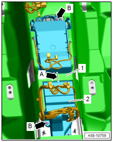
- Cut through the carpet connecting piece -1- at the position shown in the illustration -arrow A- using scissors.
- Remove the nut -arrows B-.
- Unclip the control module cover -2- from the threaded pin.
- Unclip the wiring harness from the cover using the -80-200- and free it up.
- Pull the control module cover out from under the carpet and remove it.
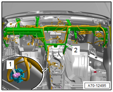
- Push aside the carpet in the area of the threaded connection, remove the nut -1- and free up the ground wires.
- Unclip the wiring harness from the center tunnel and free it up.
- Unclip the wiring harness for the instrument panel central tube -2- and free it up.
- Remove the steering column from the instrument panel central tube and lay it on the floor of the vehicle. Refer to → Suspension, Wheels, Steering; Rep. Gr.48; Steering Column; Steering Column, Removing and Installing.
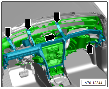
- Remove the bolts -arrows-.
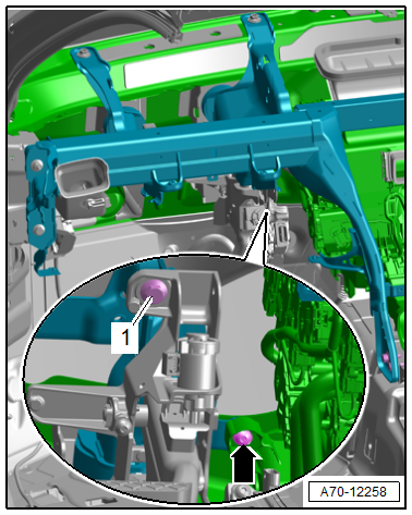
- Remove the bolt -1-.
- Remove the bolt -arrow- for the A/C unit.
 Note
Note
For reinstallation, mark the vertical and lengthwise position on the instrument panel central tube.
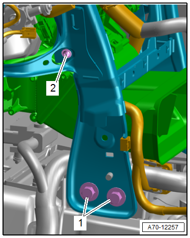
- Push aside the carpet in the area near the threaded connection and remove the bolts -1-.
- Remove the bolt -2- for the A/C unit.
- Repeat the procedure on the opposite side.
- Remove the bolt -1- and nut -2- for the instrument panel central tube
- Repeat the procedure on the opposite side.
- Unclip the wire for the instrument panel central tube disengage and free up.
Note
Two technicians are needed to remove the instrument panel central tube.
- Disengage the instrument panel central tube from the A/C unit and remove from the vehicle interior toward the rear.
Installing
- Carefully insert the instrument panel central tube in the body.
- Align the instrument panel central tube according to the marks applied to the A-pillar during removal.
- Tighten the nuts and bolts for the instrument panel central tube near the A-pillar on both the driver and front passenger sides.
Further installation is performed in reverse order of removal, while noting the following:
- Install the steering column. Refer to → Suspension, Wheels, Steering; Rep. Gr.48; Steering Column; Overview - Steering Column.
- Mounting bracket for pedal assembly. Refer to → Brake System; Rep. Gr.46; Brake Pedal; Overview - Brake Pedal.
Installation Position of Instrument Panel Central Tube, Checking
- Insert the instrument panel to test.
- Secure the instrument panel on the left and right side to the instrument panel central tube.
- Close the doors.
- Check whether the gap dimension between the instrument panel and the left and right door is even.
- Check whether the height of instrument panel aligns with the moldings in the door trim panels.
- If the adjustment is incorrect, note lateral and/or vertical deviation.
- Loosen the instrument panel central tube threaded connections.
- Adjust the instrument panel central tube according to the noted deviations.
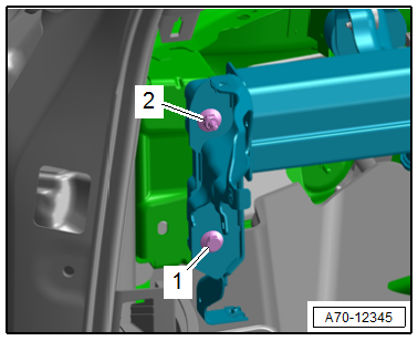
- Tighten the bolt -1- and nut -2- for the instrument panel central tube at the A-pillar on both the driver and front passenger sides.
 WARNING
Repairing pyrotechnic components (For example the airbag and seat belt tensioner) incorrectly increases the risk of injuries due to unintentional deployments when the battery is connected.
- The ignition must be on when connecting the battery.
- Make sure that no one is inside the vehicle at the time when the battery is connected.
- Equipped on some models: Install the Windshield Projection Head Up Display Control Module -J898-. Refer to → Electrical Equipment; Rep. Gr.90; Instrument Cluster; Windshield Projection Head Up Display Control Module, Removing and Installing.
- Install the windshield. Refer to → Body Exterior; Rep. Gr.64; Windshield; Windshield, Removing and Installing.
- Connect the battery ground cable with the ignition switched on. Refer to → Electrical Equipment; Rep. Gr.27; Battery; Battery, Disconnecting and Connecting.
Note
If the Airbag Indicator Lamp -K75- indicates a fault, check the DTC memory, erase it and check it again using the Vehicle Diagnostic Tester.
Installation instructions: For example tightening specifications, replacing components. Refer to → Chapter "Overview - Instrument Panel Central Tube".
READ NEXT:
 Vehicle Interior Trim Panels
Component Location Overview - Vehicle Interior Trim Panels
Component Location Overview - Vehicle Interior Trim Panels, A3 Sedan
1 - D-Pillar Trim Panel
Overview. Refer to
→ Chapte
Sill Panel, Removing and Installing
Front Sill Panel Strip, Removing and Installing
Special tools and workshop equipment required
Trim Removal Wedge -3409-
Omega Clip Tool -T40280-
Removing
- Move the front seat all the way bac
A-Pillar Trim Panel, Removing and Installing
Special tools and workshop equipment required
Trim Removal Wedge -3409-
Lever - Fuel Line -T10468-
Omega Clip Tool -T40280-
Caution
This procedure contains mandatory replaceable parts.
SEE MORE:
Messages
Text messages
Applies to: vehicles with telephone
Requirement: your mobile device must be connected
to the MMI via Bluetooth Message Access
Profile (Bluetooth MAP).
Applies to: MMI: Select on the home screen:
MESSAGES > () > e-mail (phone
1)/e-mail
(phone 2)*.
The following functions ar
Floor Heat Shield, Removing and Installing
Plenum Chamber Bulkhead Heat Shield, Removing and Installing
Removing
- Remove the plenum chamber bulkhead. Refer to
→ Chapter "Plenum Chamber Bulkhead, Removing and Installing".
- Remove the lock washers -arrows-.
- Remove the heat shield -1- from the
plenum chamber bulkhead
