Audi A4: Condenser
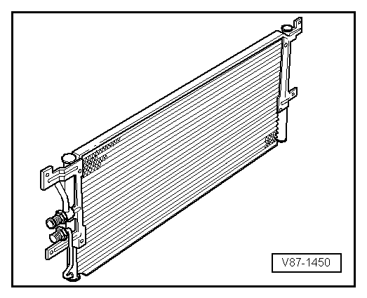
The condenser conducts heat from compressed refrigerant gas to the ambient air.
This condenses the refrigerant gas to fluid.
 Note
Note
- Depending on the version of the refrigerant circuit, the receiver/dryer is installed (integrated) either on the condenser or inside the condenser. Refer to → Heating, Ventilation and Air Conditioning; Rep. Gr.87; System Overview - Refrigerant Circuit (vehicle-specific repair manual) and the Parts Catalog.
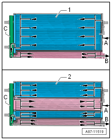
- The condenser is available in different versions and can be differentiated only by the part number on the outside. For version -1-, the condenser is divided into two areas "2 way condenser". For version -2-, the condenser is divided into four areas "4 way condenser".
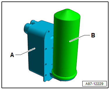
- This illustration shows a condenser with the receiver/dryer -C- installed.
- The gaseous refrigerant enters at the connection -A- into the condenser. The refrigerant is then cooled inside the condenser and becomes fluid.
- The liquid refrigerant collects in the receiver/dryer -C- (with dryer) and flows through the lower cooling area towards the connection -B-.
- Depending on the design of the condenser (interior volumes, delivery flow, etc.), the amount of the refrigerant that is needed to fill the refrigerant circuit may vary. Therefore always be sure of the correct version and allocation for the condenser. Refer to → Chapter "Refrigerant R134a Capacities" and the Parts Catalog.
Evaporator
The evaporator is available in different versions. Depending on the version and the function, the necessary heat energy of the air flow (for example, an evaporator in the A/C unit or in the battery cooling module) or flowing coolant (for example near the high voltage battery heat exchanger) is extracted for refrigerant evaporation. Refer to → Heating, Ventilation and Air Conditioning; Rep. Gr.87; System Overview - Refrigerant Circuit (vehicle-specific repair manual).
Note
Two versions of evaporator are described.
Evaporator in A/C Unit (or in Battery Cooling Module)
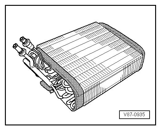
The fluid refrigerant evaporates in the evaporator pipe coils. The heat required for this is extracted from the air flowing on the evaporator ribbing. The air cools off. Refrigerant evaporates and is extracted with the absorbed heat by the A/C compressor.
A defined amount of refrigerant is supplied to the evaporator by a restrictor or expansion valve. In systems with expansion valve, the throughput is regulated so that only gaseous refrigerant escapes the evaporator outlet.
Evaporator/High Voltage Battery Heat Exchanger (Chiller)
The liquid refrigerant evaporates in evaporator (heat exchanger). The heat required for this is extracted from the flowing refrigerant. The coolant cools, the refrigerant evaporates and is extracted with the absorbed heat by the A/C compressor.
A defined amount of refrigerant is supplied to the evaporator by a restrictor (or expansion valve) and a shut off valve. The throughput of the refrigerant (for example the coolant) is regulated so that only gaseous refrigerant escapes the evaporator outlet. Refer to → Heating, Ventilation and Air Conditioning; Rep. Gr.87; System Overview - Refrigerant Circuit (vehicle-specific repair manual).
Heat Pump Operation Heater Core
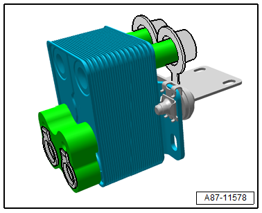
The gaseous or vaporous refrigerant that is compressed by the A/C compressor is liquefied in the A/C compressor -A- and at the same time released heat is transferred to the coolant flowing by. Refer to → Heating, Ventilation and Air Conditioning; Rep. Gr.87; Refrigerant Circuit; System Overview - Refrigerant Circuit.
Fluid Collector
In some operating conditions (for example heat pump operation) the receiver/dryer (for example on the condenser) is not incorporated in the refrigerant circuit. The fluid collector -B- collects the refrigerant, and saves it if a specific quantity of refrigerant is not needed and directs it in an uninterrupted stream to the expansion valve (in front of the evaporator in the heater and A/C unit) or to the heat exchanger in the refrigerant circuit of the high-voltage system. Refer to → Heating, Ventilation and Air Conditioning; Rep. Gr.87; Refrigerant Circuit; System Overview - Refrigerant Circuit.
READ NEXT:
 Reservoir
The reservoir collects the vaporized and gaseous mixture
coming from the evaporator to ensure the compressor only
receives gaseous refrigerant. Gaseous refrigerant is formed from
the vapor.
The ref
Expansion Valve
The expansion valve atomizes the streaming refrigerant and
controls the flow quantity so that the vapor is gaseous only at
the evaporator outlet, depending on the heat transmission.
Note
B
Quick-Release Connections on Refrigerant Lines
WARNING
The quick-release coupling connectors may be
unlocked and opened only if the refrigerant circuit is
empty.
Note
This illustration shows the quick-coupling connection with
SEE MORE:
Lower Transverse Link, Removing and Installing
Rear Lower Transverse Link, Removing and Installing
Special tools and workshop equipment required
Torque Wrench 1332 40-200Nm -VAG1332-
Engine and Gearbox Jack -VAS6931-
Engine/Gearbox Jack Adapter - Wheel Hub Support -T10149-
Caution
This procedure contains mandatory replaceable parts
Audi drive select
Introduction
Applies to: vehicles with Audi drive select
Drive select makes it possible to experience different
types of vehicle characteristics in one vehicle.
With different driving modes, the driver can
switch the setting, for example from sporty to
comfortable. This allows you to adjust the set
