Audi A4: Door Lock, Removing and Installing
 NOTICE
Risk of damaging the operating cable by deforming it.
- Never sharply bend or kink the operating cable.
Removing
- Move the door window into the "closed" position.
- Remove the door inner cover. Refer to → Chapter "Door Inner Cover, Removing and Installing".
- Turn the operating cable on the lever -1- 90º in the direction of -arrow A- and remove it from the cable bracket -2-.
- Rotate the operating cable on the door lock release lever -3- in the direction of -arrow B-.
- The operating cable must be aligned with the opening on the release lever.
- Disengage the operating cable from the release lever.
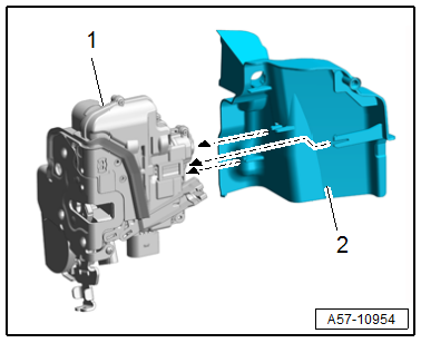
- Remove the bolts -arrows-.
- Disconnect the connector and free up the wiring harness.
- Slide the door lock -1- downward and remove it from the door.
Installing
Install in reverse order of removal.
Tightening Specifications
- Refer to → Chapter "Overview - Door Handle and Door Lock"
Door Lock Cover, Removing and Installing
Removing
- Remove the door lock. Refer to → Chapter "Door Lock, Removing and Installing".
- Release the retainers -arrows-.
- Remove the lock cylinder guide -1- from the door lock -2-.
Installing
Install in reverse order of removal and note the following:
- Push the door lock cover -2- onto the door lock -1- until it clicks into place in the direction of -arrows-.
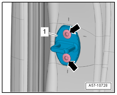
Striker, Removing and Installing
Removing
- Remove the bolts -arrows- and remove the striker -1-.
Installing
Install in reverse order of removal and note the following:
- Adjust the striker. Refer to → Chapter "Striker, Adjusting".
Tightening Specifications
- Refer to → Chapter "Overview - Door Handle and Door Lock"
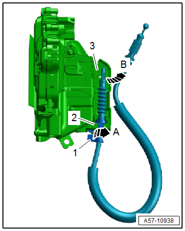
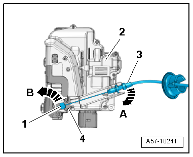
Interior Door Operating Cable, Removing and Installing
NOTICE
Risk of damaging the operating cable by deforming it.
- Never sharply bend or kink the operating cable.
Removing
- Driver side: remove the lock cylinder. Refer to → Chapter "Lock Cylinder, Removing and Installing".
- Remove the door inner cover. Refer to → Chapter "Door Inner Cover, Removing and Installing".
- Remove the bolts -arrows-.
- Push the door lock -1- to the side and disconnect the connector.
- Disengage the release cable -3- from the door lock support bracket -2- in the direction of -arrow A-.
- Turn the nipple -1- 90º in the direction of -arrow B- and remove it from the door opener release lever -4-.
Installing
Install in reverse order of removal.
Tightening Specifications
- Refer to → Chapter "Overview - Door Handle and Door Lock"
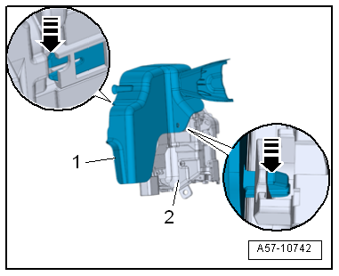
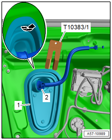
Door Inner Cover, Removing and Installing
Special tools and workshop equipment required
- Wedge Set -T10383-
- Wedge 1 -T10383/1-
Removing
- Remove the front door trim panel. Refer to → Body Interior; Rep. Gr.70; Front Door Trim Panels; Front Door Trim Panel, Removing and Installing.
- Pry the door inner cover -1- out of the inner door panel -arrow- using the -T10383/1-.
- Disengage the grommet -2- for the door opener operating cable.
Installing
Install in reverse order of removal and note the following:
- Push on the door inner cover until it engages audibly.
- Door inner cover must be installed flush.
READ NEXT:
 Window Guide, Removing and Installing
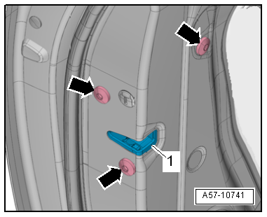
Removing
- Remove the door window. Refer to
→ Chapter "Front Door Window, Removing and Installing".
- Remove the B-pillar trim. Refer to
→ Chapter "B-Pillar Door Trim, Removi
Central Locking
Component Location Overview - Central Locking
1 -
Engine Hood Contact Switch -F266-
In the latch
Removing and installing. Refer to
→ Chapter "Engine Hood Contact Switch -F266-, Re
SEE MORE:
Front Seat Covers and Cushions
Overview - Seat Pan Cover and Cushion
Overview - Seat Pan Cover and Cushion, Seat without Seat Depth Adjuster
1 - Seat Pan
2 - Cushion
Covers and cushions, removing and installing. Refer to
→ Chapter "Seat Pan Cover and Cushion, Removing and Installing".
Cover and cush
Checking Pressures on Vehicles with Expansion Valve and Receiver/Dryer (with
Internally Regulated Compressor)
General Information
Note
Connect the A/C service station. Refer to
→ Chapter "A/C Service Station, Connecting".
Observe the test requirements. Refer to
→ Chapter "Pressures, Checking".
- With the ignition switched off, check the pressure in the
refrigerant circuit (u
