Audi A4: Central Locking
Component Location Overview - Central Locking
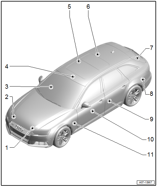
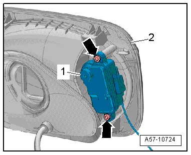
1 - Engine Hood Contact Switch -F266-
- In the latch
- Removing and installing. Refer to → Chapter "Engine Hood Contact Switch -F266-, Removing and Installing".
2 - Hood Contact Switch 2 -F329-
- In the latch
- Removing and installing. Refer to → Chapter "Engine Hood Contact Switch -F266-, Removing and Installing".
3 - Front Passenger Door Control Module -J387-
- Removing and installing. Refer to → Chapter "Driver Door Control Module -J386- and Front Passenger Door Control Module -J387-, Removing and Installing".
4 - Anti-Theft Alarm System Sensor -G578-
- Overview. Refer to → Electrical Equipment; Rep. Gr.96; Anti-Theft Alarm System; Overview - Interior Monitoring.
5 - Passenger Side Rear Door Control Module -J927-
- Equipped on some models. For allocation, refer to the Parts Catalog.
- Removing and installing. Refer to → Chapter "Left Rear Door Control Module -J388- and Right Rear Door Control Module -J389-, Removing and Installing".
6 - Fuel Filler Door Lock Motor -V155-
- Removing and installing. Refer to → Chapter "Fuel Filler Door Lock Motor -V155-, Removing and Installing".
7 - Rear Latch
- With the Rear Lid Central Locking System Motor -V53- / Rear Lid Alarm Switch -F123-, cannot be replaced separately.
- Overview. Refer to → Chapter "Overview - Rear Lid".
8 - Comfort System Central Control Module -J393-
- Removing and installing. Refer to → Chapter "Comfort System Central Control Module -J393-, Removing and Installing".
9 - Driver Side Rear Door Control Module -J926-
- Equipped on some models. For allocation. Refer to the Parts Catalog.
- Removing and installing. Refer to → Chapter "Left Rear Door Control Module -J388- and Right Rear Door Control Module -J389-, Removing and Installing".
10 - Driver Door Control Module -J386-
- Removing and installing. Refer to → Chapter "Driver Door Control Module -J386- and Front Passenger Door Control Module -J387-, Removing and Installing".
11 - Vehicle Electrical System Control Module -J519-
- Component location overview. Refer to → Electrical Equipment; Rep. Gr.97; Control Modules; Component Location Overview - Control Modules.
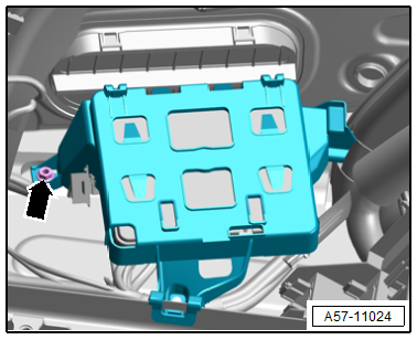
Tightening Specifications for Comfort System Central Control Module -J393- Mount
- Tighten the nut -arrow- to 3 Nm.
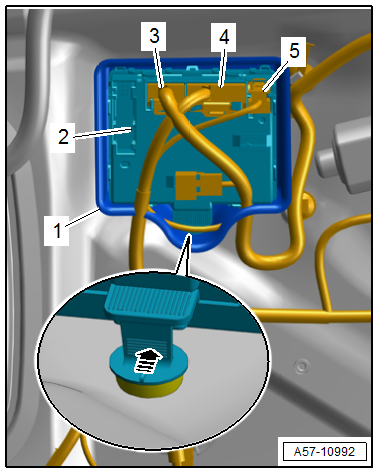
Driver Door Control Module -J386- and Front Passenger Door Control Module -J387-, Removing and Installing
Removing
- Remove the front door trim panel. Refer to → Body Interior; Rep. Gr.70; Front Door Trim Panels; Front Door Trim Panel, Removing and Installing.
- Pull the retainer and push the release downward to disconnect the connectors -3 and 4-.
- Disconnect the connector -5-.
- Press the catch in the direction of -arrow- and disengage the door control module -2- from the door body.
- Remove the rubber boot -1- from the door control module.
Installing
Install in reverse order of removal.
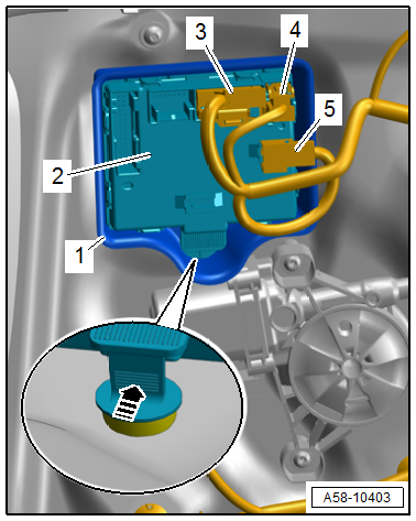
Left Rear Door Control Module -J388- and Right Rear Door Control Module -J389-, Removing and Installing
Removing
- Remove the rear door trim panel. Refer to → Body Interior; Rep. Gr.70; Rear Door Trim Panels; Rear Door Trim Panel, Removing and Installing.
- Disconnect the connector -3- by pulling the retainer and pressing the release down.
- Disconnect the connector -4-.
- Free up the connector -5- at the door control module.
- Press the catch in the direction of -arrow- and disengage the door control module -2- from the door body.
- Remove the rubber boot -1- from the door control module.
Installing
Install in reverse order of removal.
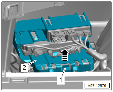
Comfort System Central Control Module -J393-, Removing and Installing
Removing
- Sedan: Loosen the luggage compartment side trim panel at the bottom by removing the tie downs. Refer to → Body Interior; Rep. Gr.70; Luggage Compartment Trim Panels; Tie Downs, Removing and Installing.
- Avant: Remove the luggage compartment floor support. Refer to → Body Interior; Rep. Gr.70; Luggage Compartment Trim Panels; Overview - Luggage Compartment Side Trim Panel.
- Open the cover for the left luggage compartment side trim panel.
- Release the retainer -1-.
- Remove the bracket -2- for the control modules upward -arrow-.
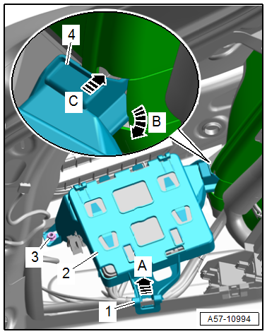
- Remove the nut -3-.
- Release the retainer in the direction of -arrow A-.
- Remove the mount -1- upward.
- Release the retainer in the direction of -arrow B- and remove the guide -4- from the body in the direction of -arrow C-.
- Remove the bracket -2- for the central control module.
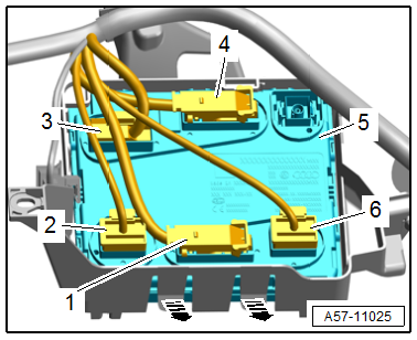
- Disconnect the connectors -1, 2, 3, 4 and 6-.
- Release the retainers -arrows- and guide the central control module -5- out of the mount.
Installing
Install in reverse order of removal.
Tightening Specifications
- Refer to → Fig. "Tightening Specifications for Comfort System Central Control Module -J393- Mount"
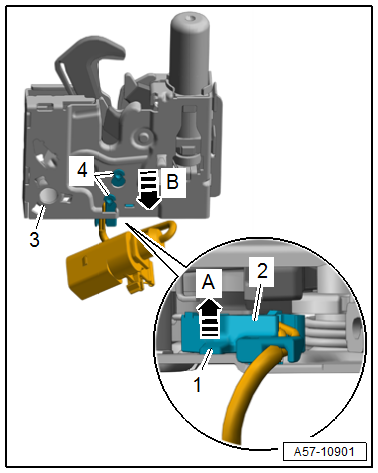
Engine Hood Contact Switch -F266-, Removing and Installing
Removing
- Remove the front latch. Refer to → Chapter "Latch, Removing and Installing".
- Lift the retaining tab -1- in the direction of -arrow A-.
- Disengage the contact switch -2- from the latch -3- in the direction of in the direction of -arrow B- and remove.
Installing
Install in reverse order of removal and note the following:
- The guide pins -4- on the contact switch must inserted correctly in the front latch.
Fuel Filler Door Lock Motor -V155-, Removing and Installing
Removing
- Remove the fuel filler door unit. Refer to → Chapter "Fuel Filler Door Unit, Removing and Installing".
- Remove the bolts -arrows-.
- Remove the fuel filler door lock motor -1- with the emergency release cable from the fuel filler door unit -2-.
- If the fuel filler door lock motor is being replaced, remove the emergency release cable for the fuel filler door lock. Refer to → Chapter "Emergency Release Cable, Removing and Installing".
Installing
Install in reverse order of removal.
Tightening Specifications
- Refer to → Chapter "Overview - Fuel Filler Door Unit"
Special Tools
Special tools and workshop equipment required
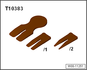
- Wedge Set -T10383-
- Wedge 1 -T10383/1-
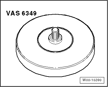
- Adhesive Strip Remover -VAS6349-
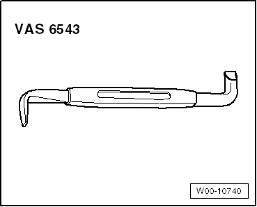
- Angled Screwdriver -VAS6543-
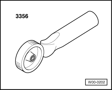
- Roller -3356-
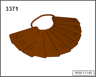
- Gauge - Gap Adjustment -3371-
- Not illustrated:
- Template -T40038/20-
READ NEXT:
 Door
Door
Overview - Door
1 -
Door
Removing and installing. Refer to
→ Chapter "Door, Removing and Installing".
2 -
Bolt
33 Nm
3 -
Door Arrester
Removing and insta
Door, Removing and Installing
Removing
- Disconnect the door cut-off connector -1-
at the B-pillar. Refer to
→ Electrical Equipment; Rep. Gr.97; Connectors.
- Tape off the B-pillar in the door arrester
SEE MORE:
Adjusting Buffer, Removing and Installing
Adjusting Buffer, Removing and Installing, Sedan
Body Adjusting Buffer
Removing
- Turn the adjusting buffer -1-
counter-clockwise -arrow- to
remove.
- Remove the adjusting buffer locking mechanism
-2- from the threaded pin.
Installing
Install in reverse order of removal and note the fo
ATF Circuit
Overview - ATF Circuit
Caution
Risk of damaging the transmission.
Remove all the plugs on the ATF lines and on the
transmission that were installed during removal.
The ATF cooling function will not work and the transmission
will be damaged if the plugs are forgotten.
WARNING
