Audi A4: Door
Overview - Door
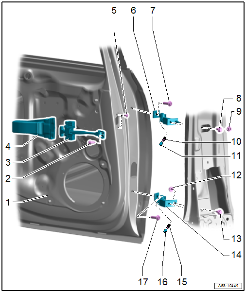
1 - Door
- Removing and installing. Refer to → Chapter "Door, Removing and Installing".
2 - Bolt
- 33 Nm
3 - Door Arrester
- Removing and installing. Refer to → Chapter "Door Arrester, Removing and Installing".
- Installation position. Refer to → Fig. "Door Arrester Installation Position".
4 - Cap
- For the door arrester
- Installation position. Refer to → Fig. "Cap Installation Position".
5 - Bolt
- 8 Nm
- Quantity: 2
6 - Upper Door Hinge
7 - Bolt
- 45 Nm
8 - Bolt
- 32 Nm
9 - Nut
- 32 Nm
10 - Set Screw
- 23 Nm
11 - Cap
12 - Nut
- 32 Nm
13 - Bolt
- 32 Nm
14 - Lower Door Hinge
15 - Set Screw
- 23 Nm
16 - Cap
17 - Bolt
- 45 Nm
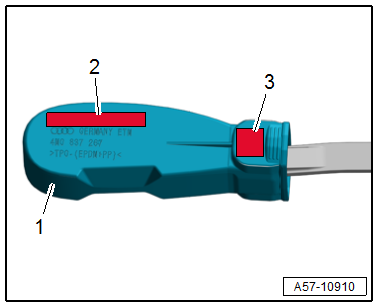
Cap Installation Position
In the installed position, the lettering on the cap -1- must be readable in the upper installation position.
2 - LEFT UPPER REAR - left / RIGHT UPPER REAR - right
3 - HL - left / HR - right
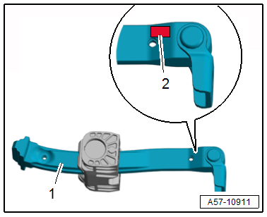
Door Arrester Installation Position
In the installed position, the lettering on the door arrester -1- must be readable in the upper installation position:
2 - HL - left / HR - right
Overview - Door Seals
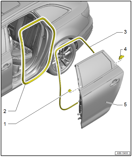
1 - B-Pillar Seal
2 - Inner Door Seal
- Removing and installing. Refer to → Chapter "Inner Door Seal, Removing and Installing".
3 - Outer Door Seal
- Replace after removing
- Removing and installing. Refer to → Chapter "Outer Door Seal, Removing and Installing".
4 - C-Pillar Seal
5 - Door
READ NEXT:
 Door, Removing and Installing
Removing
- Disconnect the door cut-off connector -1-
at the B-pillar. Refer to
→ Electrical Equipment; Rep. Gr.97; Connectors.
- Tape off the B-pillar in the door arrester
Door Arrester, Removing and Installing
Removing
- Tape off the B-pillar in the door arrester area using adhesive
tape, so that the paint will not be damaged.
- Move the door window into the "closed" position.
- Remove the r
Door Components
Overview - Window Regulator
1 -
Nut
7.5 Nm
2 -
Window Regulator
Removing and installing. Refer to
→ Chapter "Window Regulator, Removing and Installing".
3 -&nbs
SEE MORE:
Wheels and Tires
General information
Check your tires regularly for
damage, such as punctures,
cuts, cracks, and bulges. Remove
foreign objects from the tire
tread.
If driving over curbs or similar
obstacles, drive slowly and approach
the curb at an angle.
Have faulty tires or rims replaced
immediately.
Traffic incidents
Introduction
Applies to: vehicles with navigation system and online traffic
information
Fig. 147 traffic information overview
Open traffic information
Requirement: the map must be displayed.
Press on the traffic jam symbol in the side
menu on the map fig. 143.
Display traffic report details
P
© 2019-2026 Copyright www.audia4b9.com
