Audi A4: Door, Removing and Installing
Removing
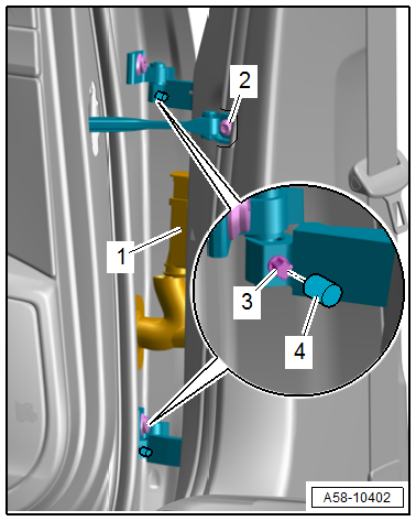
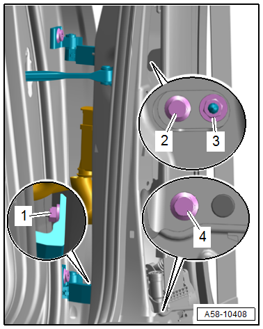
- Disconnect the door cut-off connector -1- at the B-pillar. Refer to → Electrical Equipment; Rep. Gr.97; Connectors.
- Tape off the B-pillar in the door arrester area using adhesive tape, so that the paint will not be damaged.
- Remove the door arrester bolt -2-.
- Remove the upper and lower cap -4-.
- Remove the set screw -3- from the upper and lower door hinge.
- Carefully remove the door upward out of the door hinges.
Installing
Install in reverse order of removal and note the following:
- Do not make any adjustments after installing the door.
Tightening Specifications
- Refer to → Chapter "Overview - Door"
Door, Adjusting
Adjustment Dimensions
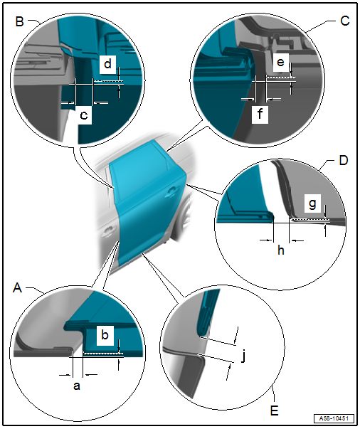
A - Rear Door to Front Door - Bottom
- Gap dimension -a- = 2.8 to 4.8 mm
- Flush dimension -b- = +- 0.7 mm
- Parallel alignment = 0.9 mm
B - Rear Door to Front Door - Top
- Gap dimension -c- = 3.5 to 4.5 mm
- Flush dimension -d- = 0/-1.0 mm
- Parallel alignment = 0.5 mm
C - Rear Door to Side Window
- Gap dimension -f- = 2.8 to 4.8 mm
- Flush dimension -e- = 0/- 1.0 mm.
- Parallel alignment = 0.5 mm
D - Rear Door to Side Panel
- Gap dimension -h- = 2.9 to 3.9 mm
- Flush dimension -g- = 0/-1.0 mm
- Parallel alignment = 0.5 mm
E - Rear Door to Body
- Gap dimension -j- = 4.0 to 6.0 mm
Door Adjustment, Checking
Special tools and workshop equipment required
- Gauge - Gap Adjustment -3371-
- Template -T40038/20-
- Adjustment dimensions. Refer to → Chapter "Adjustment Dimensions".
Door Adjustment, Checking using -T40038/20-:
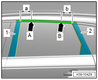
- Use the -T40038/20- to check the door frame position at two measuring points.
- Measuring point -arrow A- with dimension -a- = 100 mm (3.93 in.) from the B-pillar trim panel -1-.
- Measuring point -arrow B- with dimension -b- = 100 mm (3.93 in.) from the C-pillar trim panel -2-.
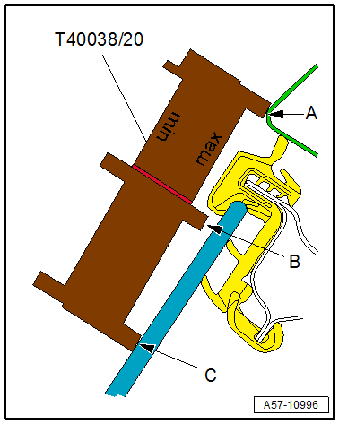
Side Adjustment, Checking using -T40038/20-:
Minimum Side Adjustment Tolerance, Checking
- Position the template on the body measuring points.
- "min" lettering on the template faces toward the vehicle.
- The template contact points -B and C- must rest on the door window.
- Point -A- should contact the roof edge, but a small gap is permitted.
- If point -A- does have a gap at the roof edge, the maximum tolerance must be checked.
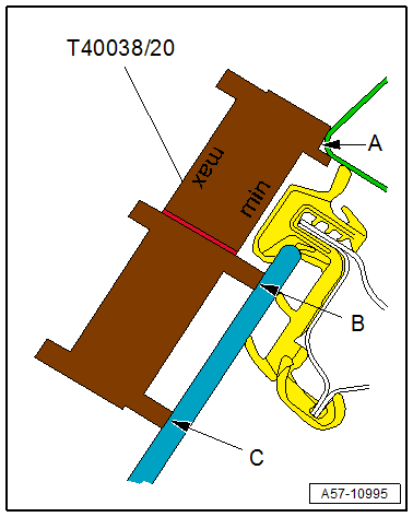
Maximum Side Adjustment Tolerance, Checking
- Position the template on the body measuring points.
- "max" lettering on the template faces toward the vehicle.
- The template contact points -A and C- must rest on the door window and on the roof edge.
- Contact point -B- may rest either on the door window, or there may be a gap.
- Adjustment is OK.
- If it is not OK, the door projects too far outward and must be adjusted.
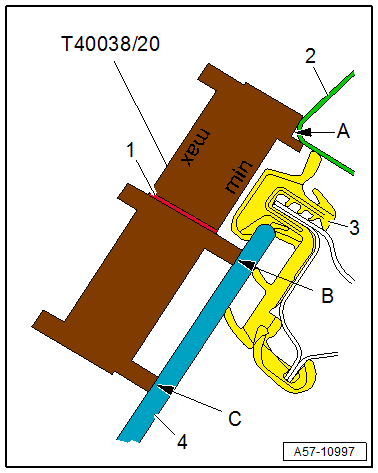
Height Adjustment, Checking using -T40038/20-:
- Position the template on the body measuring points.
- "min" lettering on the template faces toward the vehicle.
- Contact point -A- must rest against the side and bottom of the roof edge.
- The contact points -B and C- must be pressed against the door window -4-.
- For a proper height adjustment, the lower edge of the window guide -3- must be near the template marking -1-. Then the adjustment is correct.
- If not, the door must be adjusted.
Length Adjustment
- Adjustment dimensions. Refer to → Chapter "Adjustment Dimensions".
Procedure
- Remove the B-pillar lower trim panel. Refer to → Body Interior; Rep. Gr.70; Vehicle Interior Trim Panels.
- Loosen the bolts -2 and 4- and nuts -1 and 3- on the hinge and on the B-pillar.
- Adjust the door lengthwise.
- Tighten the bolts and nuts.
Tightening Specifications
- Refer to → Chapter "Overview - Door"
Side Adjustment
- Adjustment dimensions. Refer to → Chapter "Adjustment Dimensions".
Procedure
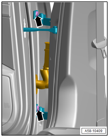
- Loosen the bolts -arrows- on the upper and lower hinge.
- Adjust the door to the center of the vehicle.
- Tighten the bolts.
Tightening Specifications
- Refer to → Chapter "Overview - Door"
Striker, Adjusting
- Adjustment dimensions. Refer to → Chapter "Adjustment Dimensions".
Procedure
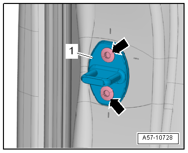
- Loosen the bolts -arrows-.
- Slide the striker -1- until the door is flush with the body contour.
- When adjusting the striker, move it only toward the center of the vehicle.
- Do not adjust the door height using the striker because the door lock will be damaged.
- When adjusted correctly, the striker must engage in the center of the door lock.
- Tighten the bolts.
Tightening Specifications
- Refer to → Chapter "Overview - Door Handle and Door Lock"
READ NEXT:
 Door Arrester, Removing and Installing
Removing
- Tape off the B-pillar in the door arrester area using adhesive
tape, so that the paint will not be damaged.
- Move the door window into the "closed" position.
- Remove the r
Door Components
Overview - Window Regulator
1 -
Nut
7.5 Nm
2 -
Window Regulator
Removing and installing. Refer to
→ Chapter "Window Regulator, Removing and Installing".
3 -&nbs
Window Regulator, Removing and Installing
Removing
- Remove the rear door window. Refer to
→ Chapter "Rear Door Window, Removing and Installing".
- Release the retainers -3 and 4- on
the threaded pins -5- for the
window re
SEE MORE:
Personalization
Users
General information
Applies to: vehicles with personalized user settings
Depending on vehicle equipment and your country,
your vehicle may be able to manage various
users in the MMI. Each user will be assigned the
settings that they last used.
Before you begin driving, you can select a user i
Steering wheel
General information
Make sure that:
The distance between your upper body and the
steering wheel is at least 10 inches (25 cm)
Your arms are bent slightly at the elbows
You have a sufficient view of the area around
the vehicle and you have a clear view of the instrument
cluster and head-up dis
