Audi A4: Overview - Subframe
Subframe
 Caution
There is a risk of damaging the threads on the subframe threaded connection to the body.
- The subframe bolts on the body must not be loosened or tightened with an impact wrench.
- Always install all bolts by hand for the first few turns.
There is a risk of damaging the suspension components.
- If the subframe mount, steering gear or subframe crossbrace are not installed correctly, do not rest the vehicle on its wheels.
- Supporting the vehicle at the subframe or the subframe crossbrace (for example, using a floor jack or similar device) is not permitted.
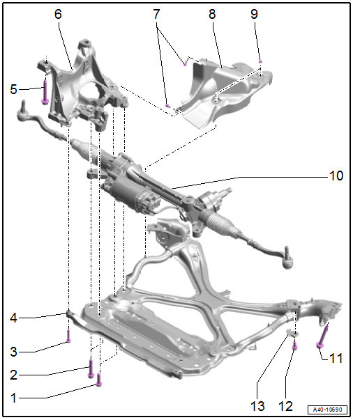
1 - Bolt
- 90 Nm +90º
- Replace after removing
2 - Fitting Bolt
- 90 Nm +90º
- Replace after removing
3 - Bolt
- 30 Nm
4 - Subframe Crossbrace
- Removing and installing. Refer to → Chapter "Subframe Crossbrace, Removing and Installing".
5 - Bolt
- 115 Nm + 180º
- Replace after removing
- Loosen and tighten together with -Item 11- → Item and -Item 12- → Item diagonally in stages
6 - Subframe
- Securing. Refer to → Chapter "Subframe, Securing".
- Lowering. Refer to → Chapter "Subframe, Lowering".
- Removing and installing. Refer to → Chapter "Subframe with Steering Gear, Removing and Installing".
7 - Bolts
- 9 Nm
8 - Shield
- Removing and installing. Refer to → Chapter "Subframe Shield, Removing and Installing".
9 - Nut
- 9 Nm
10 - Steering Gear
- Overview. Refer to → Chapter "Overview - Steering Gear".
11 - Bolt
- 115 Nm + 180º
- Replace after removing
- Loosen and tighten together with -Item 5- and -Item 12- → Item diagonally in stages
12 - Bolt
- 50 Nm + 90º
- Replace after removing
- Loosen and tighten together with -Item 5- and -Item 11- → Item diagonally in stages
13 - Clip
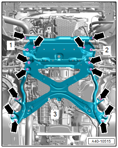
Subframe Crossbrace - Tightening Sequence
- Tighten the bolts in the steps shown in the sequence:
.png)
Stabilizer Bar
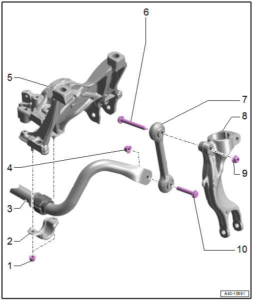
1 - Nut
- 30 Nm
- Replace after removing
- Remove and tighten evenly alternating from side to side.
2 - Clamp
3 - Stabilizer Bar
- With rubber bushing
- The rubber bushing cannot be replaced separately
- Removing and installing. Refer to → Chapter "Stabilizer Bar, Removing and Installing".
4 - Nut
- 40 Nm + 90º
- Replace after removing
- Tighten in the curb weight position. Refer to → Chapter "Wheel Bearing in Curb Weight Position, Lifting Vehicles with Coil Spring".
5 - Subframe
6 - Bolt
- Replace after removing
7 - Coupling Rod
- Removing and installing. Refer to → Chapter "Coupling Rod, Removing and Installing".
8 - Shock Absorber Fork
- Removing and installing. Refer to → Chapter "Shock Absorber Fork, Removing and Installing".
9 - Nut
- 40 Nm + 90º
- Replace after removing
- Tighten in the curb weight position. Refer to → Chapter "Wheel Bearing in Curb Weight Position, Lifting Vehicles with Coil Spring".
10 - Bolt
- Replace after removing
READ NEXT:
 Subframe, Securing
Special tools and workshop equipment required
Torque Wrench 1331 5-50Nm -VAG1331-
Torque Wrench 1332 40-200Nm -VAG1332-
Engine and Gearbox Jack -VAS6931-
Gearbox Support -T40173-
Locating Pins -
Subframe, Lowering
Special tools and workshop equipment required
Torque Wrench 1331 5-50Nm -VAG1331-
Torque Wrench 1332 40-200Nm -VAG1332-
Tensioning Straps -T10038-
Engine and Gearbox Jack -VAS6931-
Locating Pins
Subframe with Steering Gear, Removing and Installing
Special tools and workshop equipment required
Torque Wrench 1331 5-50Nm -VAG1331-
Torque Wrench 1332 40-200Nm -VAG1332-
Engine and Gearbox Jack -VAS6931-
Ball Joint Splitter -VAS251805-, not illu
SEE MORE:
Fuses
Replacing fuses
Fig. 181 Driver's side footwell (left-hand drive vehicles):
footrest 1, front passenger's side footwell (right-hand
drive vehicles): cover 2
Fig. 182 Driver's side cockpit (left-hand drive/right-hand
drive vehicles): cover (C), left side of luggage compartment:
cover (D)
Fuses are
Speed warning system
Description
Applies to: vehicles with speed warning system
The speed warning system helps the driver to
stay below a specified maximum speed. A warning
threshold can be set in the MMI for this purpose.
Once the speed slightly exceeds the stored
threshold, the speed warning system will alert
the d
© 2019-2026 Copyright www.audia4b9.com
