Audi A4: Fan Shroud, Removing and Installing
Removing
- Remove the front noise insulation. Refer to → Body Exterior; Rep. Gr.66; Noise Insulation; Overview - Noise Insulation.
- Remove the charge air cooler. Refer to → Chapter "Charge Air Cooler, Removing and Installing".
 WARNING
There is a risk of injury if the radiator fan turns on by itself.
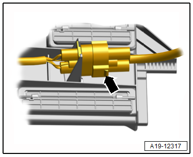
Disconnect the connectors before working near the fan shroud.
- Disconnect the radiator fan connector -arrow-.
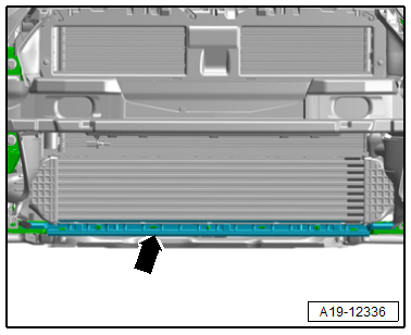
- Unclip the lower air duct -arrow-.
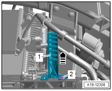
- Remove the left and right bolt -2- and push the radiator bracket -1- with the bolt toward the front in the direction of -arrow-.
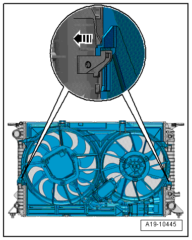
- Press the fan shroud left and right locking tabs at the same time in the direction of -arrow- and remove the fan shroud upward from the radiator.
Installing
Install in reverse order of removal and note the following:
- Install the charge air cooler. Refer to → Chapter "Charge Air Cooler, Removing and Installing".
Tightening Specifications
- Refer to → Chapter "Overview - Radiator/Radiator Fan"
- Refer to → Body Exterior; Rep. Gr.66; Noise Insulation; Overview - Noise Insulation.
Radiator Fan -V7-, Removing and Installing
Removing
- Remove the fan shroud. Refer to → Chapter "Fan Shroud, Removing and Installing".
- Free up the wiring harness.
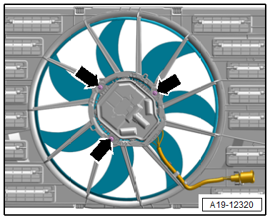
- Remove the bolts -arrows- and then remove the radiator fan.
 Caution
Risk of noises due to an imbalanced fan wheel.
Do not remove the counter-balancing clamps from the fan wheel.
Installing
Install in reverse order of removal and note the following:
- Install the fan shroud. Refer to → Chapter "Fan Shroud, Removing and Installing".
Tightening Specifications
- Refer to → Chapter "Overview - Radiator/Radiator Fan"
Special Tools
Special tools and workshop equipment required
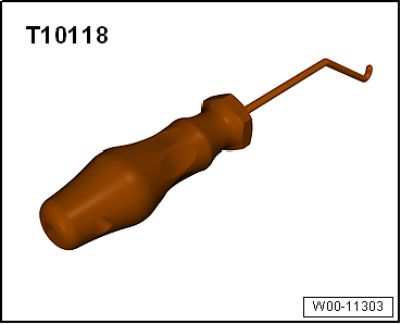
- Elbow Assembly Tool -T10118-
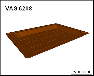
- Coolant Collection System -VAS5014- or Shop Crane - Drip Tray -VAS6208-
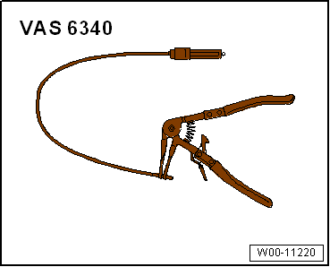
- Hose Clip Pliers -VAS6340-
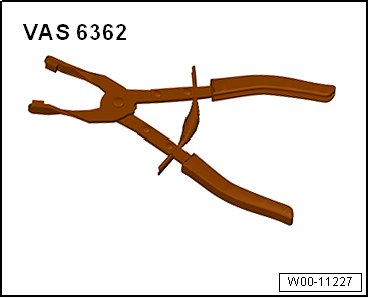
- Hose Clip Pliers -VAS6362-
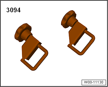
- Hose Clamps - Up To 25mm -3094-
READ NEXT:
 Turbocharger, G-Charger
Turbocharger
All procedures and components are described under:
→ Servicing - 4-Cylinder 2.0L 4V TFSI Engine; Rep. Gr.21; Turbocharger;
Turbocharger, Removing and Installing.
Charge
Injection System
Component Location Overview - Injection System
Component Location Overview - Engine Compartment
1 - Oxygen Sensor after Catalytic Converter -G130- with Heater for
Oxygen Sensor 1 after Cat
SEE MORE:
Radiator/Radiator Fan
Overview - Radiator/Radiator Fan
1 - Radiator
Removing and installing. Refer to
→ Chapter "Radiator, Removing and Installing".
After replacing, replace entire amount of coolant
2 - Drain Plug
1.5 to 3 Nm
3 - O-ring
Replace after removing
4 -
Windshield Wiper/Washer System
Washer Fluid Hoses
Washer Fluid Line Hose Connections, Disconnecting and Connecting
Various hose couplings are used to connect the hoses to the
washer fluid pumps and spray jets or as coupling points.
Unsecured Hose Coupling
- To disconnect the connection, pull both parts of the
coupling apar
