Audi A4: General Information
High pressure side are the condenser, receiver/dryer and restrictor or expansion valve to separate the high and low pressure liquid ends.
High pressure results from the restrictor or expansion valve forming a constriction and causing the refrigerant to accumulate, thus leading to an increase in pressure and temperature.
Excess pressure occurs if too much refrigerant or refrigerant oil is used, the condenser is contaminated, the radiator fan is malfunctioning, the system is blocked or there is moisture in the refrigerant circuit (icing-up of restrictor or expansion valve).
Low pressure side are the evaporator, reservoir, evaporator temperature sensor and A/C compressor to separate high and low pressure gas ends.
A drop in system pressure can be caused by loss of refrigerant, the restrictor or expansion valve (no constriction), a malfunctioning A/C compressor or an iced-up evaporator.
Mechanically Driven A/C Compressor
The A/C compressor is driven by a ribbed belt or a input shaft, which is driven by the vehicle engine.
A/C Compressor with A/C Clutch
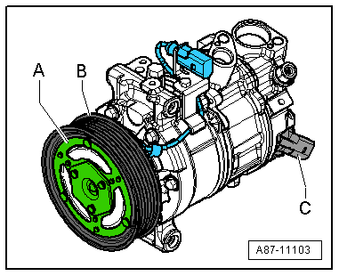
- An electromagnetic clutch -A- attached to A/C compressor provides the power link between the ribbed belt pulley -B- and A/C compressor crankshaft with A/C system switched on.
- An overload safeguard attached to the clutch plate or in the A/C compressor solenoid coil is tripped if the compressor does not move freely, thus protecting the belt drive against overload.
A/C Compressor without A/C Clutch
- An overload safeguard attached to the pulley of the compressor -B- is tripped if the compressor does not move freely, thus protecting the belt drive against overload.
All A/C Clutch
The A/C compressor extracts the refrigerant gas from the evaporator, compresses it and relays it to the condenser.
 Note
Note
- The A/C compressor contains refrigerant oil, which can be mixed with refrigerant R134a under any temperature.
- The data plate lists the type of refrigerant required for the A/C compressor. A regulator valve regulates pressure within the specified range (control characteristics) on the low pressure side.
- A/C compressors with or without an A/C clutch are currently controlled externally by a regulator valve -C-.
- On A/C compressors without an A/C clutch, the engine is only to be started following complete assembly of the refrigerant circuit.
- So that the A/C compressor does not get damaged when the refrigerant circuit is empty, the A/C clutch is turned off and the A/C Compressor Regulator Valve -N280- is no longer activated (A/C compressor runs at idle with engine).
- If the refrigerant circuit is empty, a A/C compressor without A/C Clutch -N25- with (A/C Compressor Regulator Valve -N280-) is switched to internal lubrication by way of a valve.
- Depending on the A/C compressor version, there may be a valve installed on the high pressure side of the A/C compressor, which prevents the liquid refrigerant from flowing back into the compressor once the A/C is turned off. If an A/C compressor with this valve is installed in a vehicle with a refrigerant circuit having an expansion valve, then it may take some time until the pressure in the high pressure side decreases (the expansion is cold and the pressure in the low pressure side quickly increases after it is turned off, the expansion valve closes and the refrigerant flows slowly into the low pressure side). If the A/C compressor is switched on, the pressure on the low pressure side goes down, the expansion valve open and the refrigerant can flow of the low pressure side.
- The electromagnetic clutch -A- is activated only when the regulator valve -C- is activated on an A/C compressor with an electromagnetic clutch -A- and with a regulator valve -C-. Refer to → Heating, Ventilation and Air Conditioning; Rep. Gr.87; System Overview - Refrigerant Circuit.
Electrically Driven A/C Compressor for Vehicles with High Voltage System
Vehicles with a High-Voltage System (Hybrid Vehicles)
Extremely Dangerous Due to High-Voltage
The high-voltage system is under high-voltage. Death or serious bodily injury by electric shock.
- Individuals with electronic/medical life- and health sustaining machines in or on their person cannot perform any work on high-voltage systems. Life- and health sustaining machines are for example pain killer pumps, implanted defibrillators, pacemakers, insulin pumps, and hearing aids.
- Have the high-voltage system de-energized by a qualified person.
There is a Risk Of Injury from the Engine Starting Unexpectedly
On electric - hybrid vehicles an active ready mode is difficult to identify. Parts of the body can be clamped or pulled.
- Turn off the ignition.
- Place the ignition key outside of the vehicle interior.
Risk of Damaging the High-Voltage Cables
Misuse can damage the insulation of high-voltage cables or high-voltage connectors.
- Never support objects on the high-voltage cables and the high-voltage connectors.
- Never support tools on the high-voltage cables and the high-voltage connectors.
- Never sharply bend or kink the high-voltage cables.
- When connecting pay attention to the coding of the high-voltage connectors.
- For all procedures on vehicles with high-voltage system pay attention to the additional warning message for these vehicles. Refer to → Chapter "Warnings when Working on Vehicles with High Voltage System".
- If procedures are necessary near components of the high-voltage system "perform a visual inspection of the damage of the high-voltage components and lines". Refer to → Chapter "Performing a Visual Inspection of Damage to High Voltage Components and Cables".
- If work on the components of the high-voltage system is necessity, de-energize the high-voltage system. Refer to → Rep. Gr.93; High-Voltage System, De-Energizing or → Electrical Equipment; Rep. Gr.93; High-Voltage System, De-Energizing.
- Charge the vehicle battery, for example, using the Battery Charger -VAS5904- in the battery support mode to minimize the number of automatic starts during the test- and measuring procedures while the ready mode is active. Refer to → Electrical Equipment General Information; Rep. Gr.27; Battery, Charging and → High Voltage Vehicle General Information; Rep. Gr.93; High-Voltage System General Warnings.
- For testing and measurement procedures that require the ready mode to be active or the ignition to be switched on, the selector lever must be in the "P" position and the parking brake must be activated. The required tools must be placed so that they do not come into contact with any rotating components in the engine and they must also not go into the vicinity of the rotating components when the engine is running.
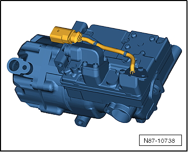
Electrically-Driven A/C Compressor
 WARNING
Risk of short circuit
The A/C compressor works with up to 288 volts at 800 to 8,600 RPM.
Do not touch the A/C compressor when the ignition is turned on or when the drive machines are activated because of the short circuit risk.
- The A/C compressor extracts the refrigerant gas from the evaporator, compresses it and relays it to the condenser.
- The electric motor for the A/C compressor is powered with voltage from the Electric Drive Power and Control Electronics -JX1-.
- The A/C Compressor Control Module -J842- integrated in the A/C compressor controls the rotation and thereby the output for the A/C compressor (Electrical A/C Compressor -V470-) corresponding with the Data bus receiving requirements. Use the Vehicle Diagnostic Tester in the "Guided Fault Finding" Function for the A/C System and the Battery Regulation.
- There is no A/C Compressor Regulator Valve -N280- installed in the electrically-driven A/C compressor.
- Check the attachment points on the A/C compressor and the bracket prior to installation. The contact surfaces must be clean and free of rust and grease. Otherwise, repair the contact surfaces with the Contact Surface Cleaning Set -VAS6410-. Refer to → Electrical Equipment General Information; Rep. Gr.97; Wire and Connector Repair.
Note
- Check the amount of refrigerant oil in the new A/C compressor if the A/C Compressor Control Module -J842- is faulty. Do not flush the refrigerant circuit with R134a.
- The A/C Compressor Control Module -J842- and the Electrical A/C Compressor -V470- are one component and are currently not able to be separated.
- There is no A/C Compressor Regulator Valve -N280- installed in the electrically driven A/C compressor. The A/C compressor output is regulated externally by the A/C compressor speed. Refer to → Wiring diagrams, Troubleshooting & Component locations and use the Vehicle Diagnostic Tester in the "Guided Fault Finding" Function for the A/C System and the Battery Regulation.
- The electrically-driven A/C compressor functions according to the principle of a spiral charger (similar to a G-charger).
- The A/C compressor contains refrigerant oil, which can be mixed with refrigerant R134a under any temperature.
- The data plate lists the type of refrigerant required for the A/C compressor.
- The installed electronics are controlled by the speed of the A/C compressor power output (and the pressure on the low pressure side) within the specified range (control characteristic).
- The engine should only be started if the refrigerant circuit is completely assembled.
- The A/C compressor is equipped with a protected oil supply, this prevents A/C compressor damage in the event that the system is empty. This means that approximately 40 to 50 cm3 of refrigerant oil remains in the A/C compressor.
- The electrically-driven A/C compressor has a relief valve like the mechanically-driven A/C compressor.
- Hybrid drive on vehicles with battery cooling is only possible with a fully charged A/C system in which there are no stored errors. Use the Vehicle Diagnostic Tester in the "Guided Fault Finding" Function for the A/C System and the Battery Regulation.
- After the installation of the electrically-driven A/C compressor and the subsequent filling of the refrigerant circuit, start the A/C compressor for the first time using the "compressor intake" function for the basic setting. The A/C compressor may otherwise become damaged if before installation, refrigerant oil was improperly stored in the A/C compressor compression chamber. Use the Vehicle Diagnostic Tester in the "Guided Fault Finding" Function for the A/C System and the Battery Regulation.
- Only activate the electrically-driven A/C compressor when the refrigerant circuit is filled. The A/C compressor may become damaged if the A/C compressor is run when the refrigerant circuit is empty. Use the Vehicle Diagnostic Tester in the "Guided Fault Finding" Function for the A/C System and the Battery Regulation.
READ NEXT:
 Condenser
The condenser conducts heat from compressed refrigerant gas
to the ambient air.
This condenses the refrigerant gas to fluid.
Note
Depending on the version of the refrigerant circuit, the
r
Reservoir
The reservoir collects the vaporized and gaseous mixture
coming from the evaporator to ensure the compressor only
receives gaseous refrigerant. Gaseous refrigerant is formed from
the vapor.
The ref
Expansion Valve
The expansion valve atomizes the streaming refrigerant and
controls the flow quantity so that the vapor is gaseous only at
the evaporator outlet, depending on the heat transmission.
Note
B
SEE MORE:
Adjusting the display
Fig. 6 Center display: adjusting the display
Switching the view
Applies to: Audi virtual cockpit
Press the VIEW button to switch between the
default view (1) and the enhanced view (2).
Adjusting the layout
Applies to: Audi virtual cockpit
Depending on the vehicle equipment, various layouts
may
Battery Charger -VAS5906-
WARNING
Risk of injury. Follow all warning messages and
safety precautions. Refer to
→ Chapter "Warnings and Safety Precautions".
WARNING
Do not check or charge a Battery -A- when the visual
indicator has "no color or is
bright yellow". Jump starting must not be used!
Th
