Audi A4: Overview - Drive Axle
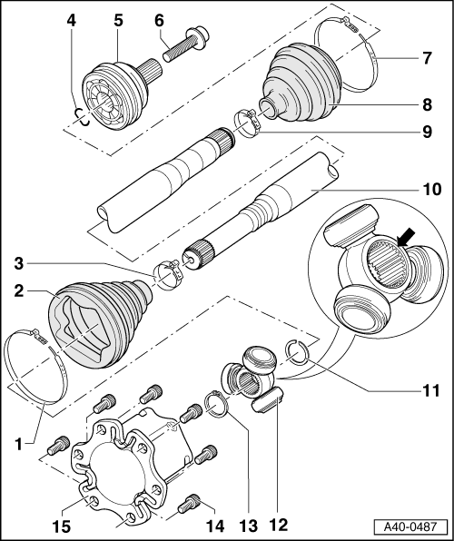
1 - Clamp
- Replace after removing
- Tensioning. Refer to → Chapter "Clamp on Triple Roller Joint and Outer Joint, Tensioning".
2 - CV Boot
- If the drive axle has a peened triple roller joint, then the triple roller joint has an adapter installed
- The CV boot must fit in the groove and on the joint contour.
3 - Clamp
- Replace after removing
- Tensioning. Refer to → Chapter "Clamp on Triple Roller Joint and Outer Joint, Tensioning".
4 - Circlip
- Replace after removing
- Insert into ring groove of shaft before installation (not visible on installed joint)
- Before installing CV joint, align the circlip in the center with opening facing upward.
5 - Outer CV Joint
- Completely replace
- Removing.
- Checking using the Vehicle Diagnostic Tester. Refer to → Chapter "Outer CV Joint, Checking".
- Installing.
- Lubricating.
- Before installing the CV joint, thinly coat the profile shaft splines with the grease used in the joint.
6 - Bolt
- Replace after removing
- Clean the threads in the CV joint with for example a thread tap.
- Drive axle threaded connection, loosening and tightening. Refer to → Chapter "Drive Axle Threaded Connection, Loosening and Tightening".
7 - Clamp
- Replace after removing
- Tensioning. Refer to → Chapter "Clamp on Triple Roller Joint and Outer Joint, Tensioning".
8 - CV Boot
- Check for tears and scuffing
- 9 - Clamp
- Replace after removing
- Tensioning. Refer to → Chapter "Clamp on Triple Roller Joint and Outer Joint, Tensioning".
10 - Drive Axle
- Different versions:
- Triple roller joint AAR 2600 i with an outer CV joint with 85.2 mm diameter.
- Triple roller joint AAR 3300 i with an outer CV joint with 94 mm or 98.9 mm diameter.
- Triple roller joint AAR 3700 i with an outer CV joint with 102.7 mm diameter.
- Allocation. Refer to the Parts Catalog.
- Removing and installing. Refer to → Chapter "Drive Axle, Removing and Installing".
- Triple roller joint allocation. Refer to → Fig. "Triple Roller Joint Allocation".
- Drive axle, disassembling and assembling. Refer to → Chapter "Drive Axle, Disassembling and Assembling".
11 - Circlip
- Replace after removing
- Insert in shaft groove
12 - Triple Roller Star
- Mark the installed position for reinstallation.
- Disassembling and assembling. Refer to → Chapter "Drive Axle, Disassembling and Assembling".
- Before installing the triple roller star, thinly coat the profile shaft splines with the grease used in the joint.
13 - Circlip
- Replace after removing
- Insert in shaft groove
14 - Bolt
- M10: 50 Nm + 90º
- M12: 90 Nm + 90º
- Replace after removing
15 - Joint
- Disassembling and assembling. Refer to → Chapter "Drive Axle, Disassembling and Assembling".
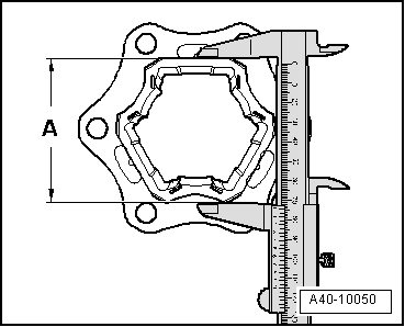
Triple Roller Joint Allocation
- Determine the dimension -A- with the clamps open and the CV boot pushed back.
- Dimension -A- = approximately 74 mm: drive axle with triple roller joint AAR 2600 i
- Drive axle with Triple Roller Joint AAR 2600 i, disassembling and assembling. Refer to → Chapter "Drive Axle, Disassembling and Assembling, Triple Roller Joint AAR 2600 i and AAR 3300 i".
- Dimension -A- = approximately 77 mm: drive axle with triple roller joint AAR 3300 i
- Drive axle with Triple Roller Joint AAR 3300 i, disassembling and assembling. Refer to → Chapter "Drive Axle, Disassembling and Assembling, Triple Roller Joint AAR 2600 i and AAR 3300 i".
- Dimension -A- = approximately 82 mm: drive axle with triple roller joint AAR 3700 i
- Drive axle with Triple Roller Joint AAR 3700 i, disassembling and assembling. Refer to → Chapter "Drive Axle, Disassembling and Assembling, Triple Roller Joint AAR 3700i".
Grease Quantity and Type
- Grease joint again when replacing CV boot.
- Pay attention to the grease type for the outer and inner joint. Refer to the Parts Catalog.
.png)
1) This amount goes into the joint through the inner splines on the ball hub. Apply the remainder on the front side of the joint under the boot.
READ NEXT:
 Drive Axle, Removing and Installing
Special tools and workshop equipment required
Torque Wrench 1332 40-200Nm -VAG1332-
Caution
This procedure contains mandatory replaceable parts.
Refer to component overview and parts cata
Drive Axle, Disassembling and Assembling
Drive Axle, Disassembling and Assembling, Triple Roller Joint AAR 2600 i
and AAR 3300 i
Special tools and workshop equipment required
Press Plate -VW401-
Press Plate -VW402-
Press Piece - Rod -VW
CV Joint, Servicing
Outer CV Joint, Removing
- Clamp the drive axle in a vise with protective covers.
- Open both clamps and remove the CV boot from the outer
joint.
- Drive out the CV joint from the driv
SEE MORE:
Service Station, Connecting with Connections on Low- and High Pressure Side
of Refrigerant Circuit
Servicing Station, Connecting for Measuring and Testing
- Turn off the ignition.
- Connect the service station to the power supply.
- Connect the quick-release coupling adapter to the charging
hoses of service station (handwheels not screwed in/hand
shut-off valve not open).
-
Windshield Wiper/Washer System
Washer Fluid Hoses
Washer Fluid Line Hose Connections, Disconnecting and Connecting
Various hose couplings are used to connect the hoses to the
washer fluid pumps and spray jets or as coupling points.
Unsecured Hose Coupling
- To disconnect the connection, pull both parts of the
coupling apar
