Audi A4: CV Joint, Servicing
Outer CV Joint, Removing
- Clamp the drive axle in a vise with protective covers.
- Open both clamps and remove the CV boot from the outer joint.
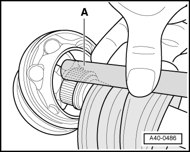
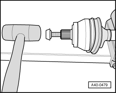
- Drive out the CV joint from the drive axle with a copper or brass mandrel -A- on the inner ring.
- Remove joint and CV boot.
Outer CV Joint, Installing
- The CV boot and the drive axle must be free of grease.
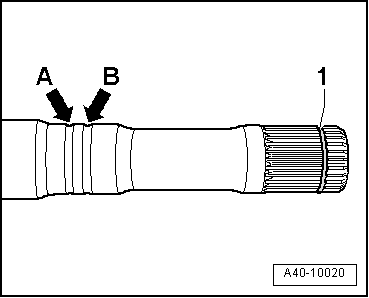
- Replace the circlip -1- after removing.
- Slide on the small clamp with the CV boot.
- Position the CV boot in the outer groove -arrow B-.
- Inner groove -arrow A- remains visible "identification groove" (for correct installation of CV boot).
- Add the specified quantity of grease to the inside of the joint.
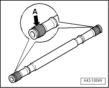
- Before installing the joint, the splines -arrow A- must be lightly coated with grease used in the joint.
- Insert the circlip into the groove on the shaft.
- Slide on the CV joint up to the circlip.
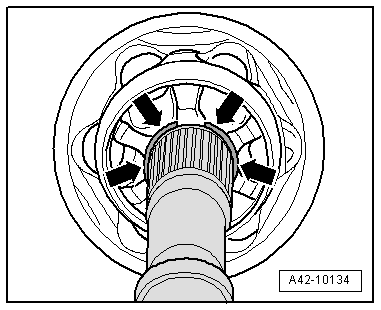
- Align the circlip at center with opening upward -arrows-.
- Install the old drive axle screw in the joint.
- Drive joint onto the drive axle with a plastic mallet until the circlip engages.
- Add the specified quantity of the grease into the joint on the CV boot side.
- Slide the CV boot onto the joint.
- Bleed the CV boot.
- Make sure the CV boot is seated on the joint correctly.
- The CV boot must fit in the groove and on joint contour.
- Tension the clamps on the outer joint. Refer to → Chapter "Clamp on Triple Roller Joint and Outer Joint, Tensioning".
READ NEXT:
 Outer CV Joint, Checking
It is necessary to disassemble the joint whenever replacing
the grease or if the ball surfaces show wear or damage.
Disassembling
- Mark the position of the ball hub -2-
to ball cage -3- and to
Clamp on Triple Roller Joint and Outer Joint, Tensioning
Note
Depending on the version of the clamp, use the following
tools:
Special tools and workshop equipment required
Torque Wrench 1331 5-50Nm -VAG1331-
Clamping Pliers -VAG1682A-
Locking P
Special Tools
Special tools and workshop equipment required
Shock Absorber Set -T10001-
Tensioning Strap -T10038-
Tripod Joint Tool -T10065-
Engine/Gearbox Jack Adapter - Wheel Hub Support -T10149-
SEE MORE:
Electronic Stabilization
Control
Description
Electronic Stabilization Control (ESC) supports
driver safety. It reduces the risk of slipping and
improves driving stability. ESC detects critical situations,
such as if the vehicle is oversteering or
understeering, or if the wheels are spinning.
The brakes are applied or the motor t
Compressor, Replacing without the Need for Flushing Refrigerant Circuit
Note
Cleaning the refrigerant circuit means flushing with
refrigerant R134a. Refer to
→ Chapter "Refrigerant Circuit, Cleaning (Flushing), with
Refrigerant R134a".
If a faulty A/C compressor is replaced with an A/C
compressor from another manufacturer check for the A/C
compres
