Audi A4: Drive Axle, Disassembling and Assembling
Drive Axle, Disassembling and Assembling, Triple Roller Joint AAR 2600 i and AAR 3300 i
Special tools and workshop equipment required
- Press Plate -VW401-
- Press Plate -VW402-
- Press Piece - Rod -VW408A-
- Press Piece - Rod -VW411-
- Press Piece - 31.5mm -VW416B-
- Press Piece - Multiple Use -VW447H-
- Slide Hammer Set -VW771-
- Clamping Pliers -VAG1682A- with Clamping Pliers - Jaws -VAG1682A/1-
- Tripod Joint Tool -T10065-
- Assembly Tool -T10065/1-
- Triple Roller Assembly Tool -T10065/5-
- Triple Roller Assembly Tool -T10065/6-
- Triple Roller Assembly Tool -T40018- for driveshafts with triple roller joint AAR 3300 i
- Triple Roller Assembly Tool -T40084- for driveshafts with triple roller joint AAR 2600 i
- Pneumatic Hydraulic Press -VAS6654-
- Commercially available locking ring pliers.
 Note
Note
- The procedure for drive axles with triple roller joint AAR 2600 i and AAR 3300 i is the same, but with the following difference:
- The -T40084- is used for the triple roller joint AAR 2600 i.
- The -T40018- is used for the triple roller joint AAR 3300 i.
Disassembling
- Clamp the drive axle horizontally in a vise with protective covers.
Note
Make sure the drive axle is not damaged.
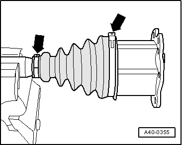
- Open the clamps -arrows-.
- Slide back the CV boot.
 Caution
There is a risk of noise while driving due to a changed installation position.
For reinstallation, mark the installation position of the joint to the drive axle using, for example, a waterproof felt-tip pen.
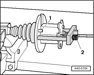
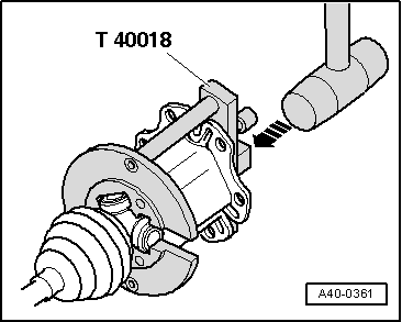
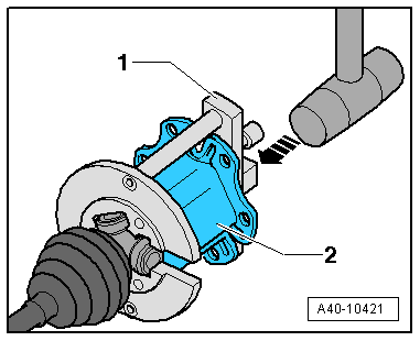
- Guide the -T40018- or -T40084- behind the joint.
- The guide pins -1- must rest on the outer joint.
- Bring the -T40018- or -T40084- to rest on the joint by turning the knurled bolts -2-.
Note
- The joint must be secured without any play in the -T40018- or -T40084-.
- Only tighten the knurled bolts hand tight.
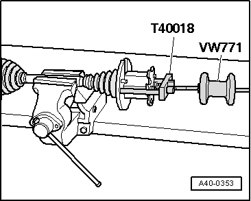
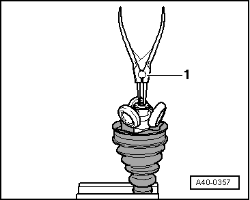
- Install the -VW771- in the Triple Roller Assembly Tool -T40018- or -T40084-.
- Remove the joint horizontally with the -VW771-.
- Leave the joint in the -T40018- or -T40084-.
Caution
There is a risk of noise while driving due to a changed installation position.
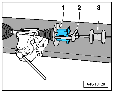
For reinstallation, mark the drive axle installation position -1- to the triple roller star -2- using, for example, a waterproof felt-tip pen.
- Remove grease with a lint-free cloth.
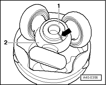
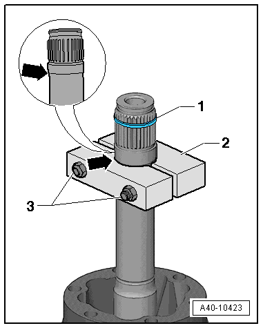
- Remove the circlip with locking ring pliers -1-.
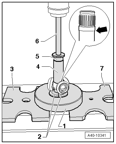
- Arrange the special tools as shown.
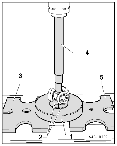
1 - -T10065/1-
2 - -T10065/5-
3 - -VW401-
4 - -VW408A-
5 - -VW402-
- The -T10065/5- must rest on the base body of the triple roller star
- The -T10065/5- must not touch the rollers; move the rollers to the side if necessary.
- Press the triple roller star off the drive axle.
- Remove the CV boot.
- Remove the grease on the shaft splines.
- Check the roller body and ball cage for wear.
- Clean drive axle and housing.
Assembling
- Slide on the small clamp with the CV boot.
- Position the CV boot between the -arrows- on the drive axle.
- Before installing the joint or triple roller star, the splines -arrow A- must be lightly coated with grease used in the joint.
- Place the triple roller star on the shaft according to the applied mark and drive on all the way.
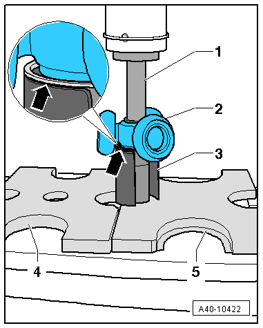
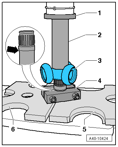
- Arrange the special tools as shown.
1 - -T10065/1-
2 - -T10065/6-
3 - -VW401-
4 - -VW416B-
5 - -VW447H-
6 - -VW411-
7 - -VW402-
- The -T10065/6- must attach to the bottom of the bead -arrow- in the drive axle.
- The -T10065/6- must not touch the rollers; move the rollers to the side if necessary.
- Install the circlip with locking ring pliers -1-.
- The circlip must engage audibly, and the triple roller star must lie on the circlip with no gap.
- Press the drive axle grease from the repair kit into the rear side of the triple roller joint.
- Lightly grease the roller body.
- Press the joint over the triple roller star using a plastic mallet in the direction of the -arrow-. Make sure roller body does not tilt during this.
Note
-T40018- is shown in the example.
- Push remaining amount of grease in the CV boot.
- Make sure the CV boot is seated on the joint correctly.
- The CV boot must fit in the groove and on joint contour.
- Mount and tighten the clamps on the triple roller joint. Refer to → Chapter "Clamp on Triple Roller Joint and Outer Joint, Tensioning".
Drive Axle, Disassembling and Assembling, Triple Roller Joint AAR 3700i
Special tools and workshop equipment required
- Press Plate -VW401-
- Press Plate -VW402-
- Press Piece - Rod -VW409-
- Press Piece - Multiple Use -VW412-
- Press Piece - 37mm -VW416B-
- CV Joint Press Sleeve -VW522-
- Slide Hammer Set -VW771-
- Press Block -40-204A-
- Vibration Damper Assembly Tool -T40236-
- Pneumatic Hydraulic Press -VAS6654-
- Commercially available locking ring pliers.
Disassembling
- Clamp the drive axle horizontally in a vise with protective covers.
Note
Make sure the drive axle is not damaged.
- Open the clamps -arrows-.
- Slide back the CV boot.
Caution
There is a risk of noise while driving due to a changed installation position.
For reinstallation, mark the installation position of the joint to the drive axle using, for example, a waterproof felt-tip pen.
- Guide the -T40236- behind the joint.
- The guide pins -1- must rest on the outer joint.
- Move the -T40236- until it rests on the joint by turning knurled screws -2-.
Note
- Secure the joint without play in the -T40236-.
- Only tighten the knurled bolts hand tight.
- Install the -VW771--3- in the -T40236--2-.
- Remove the joint -1- horizontally with the -VW771-.
- Leave the joint in the -T40236-.
Caution
There is a risk of noise while driving due to a changed installation position.
For reinstallation, mark the installation position of the drive axle -1- to the triple roller star -2- using, for example, a waterproof felt-tip pen -arrow-.
- Remove grease with a lint-free cloth.
- Remove the circlip with locking ring pliers -1-.
- Arrange the special tools as shown.
1 - -VW409-
2 - Triple Roller Star
3 - -VW522-
4 - -VW401-
5 - -VW402-
- The -VW522- must rest on the circlip -arrow-. The circlip is removed together with the triple roller star from the drive axle.
- The -VW522- must not touch the rollers; move the rollers to the side if necessary.
- Press the triple roller star off the drive axle.
- Remove the CV boot.
- Remove the grease on the shaft splines.
- Check the roller body and ball cage for wear.
- Clean drive axle and housing.
Assembling
- Slide on the small clamp with the CV boot.
- Position the CV boot between the -arrows- on the drive axle.
- Before installing the joint or triple roller star, the splines -arrow A- must be lightly coated with grease used in the joint.
- Install the -40-204A--2- as shown.
- The -40-204A- must attach to the bottom of the bead -arrow- in the drive axle.
- Tighten the nuts -3- hand tight.
- Insert the new circlip -1- up to the center of the splines.
- Place the triple roller star on the shaft according to the applied mark and drive on all the way.
- Arrange the special tools as shown.
1 - -VW412-
2 - -VW416B-
3 - Triple Roller Star
4 - -40-204A-
5 - -VW402-
6 - -VW401-
- The -VW416B- faces the triple roller star with the larger inner diameter.
- The -40-204A- must attach to the bottom of the bead -arrow- in the drive axle.
- The -40-204A- must not touch the rollers; move the rollers to the side if necessary.
- Press on the triple roller star.
- The circlip must engage audibly, and the triple roller star must lie on the circlip with no gap.
- Install the circlip with locking ring pliers -1-.
- Press the drive axle grease from the repair kit into the rear side of the triple roller joint.
- Lightly grease the roller body.
- Push the joint -2- over the triple roller star using a plastic mallet -arrow-. Make sure roller body does not tilt during this.
- 1 - Vibration Damper Assembly Tool -T40236-
- Push remaining amount of grease in the CV boot.
- Make sure the CV boot is seated on the joint correctly.
- The CV boot must fit in the groove and on joint contour.
- Mount and tighten the clamp on the triple roller joint. Refer to → Chapter "Clamp on Triple Roller Joint and Outer Joint, Tensioning".
READ NEXT:
 CV Joint, Servicing
Outer CV Joint, Removing
- Clamp the drive axle in a vise with protective covers.
- Open both clamps and remove the CV boot from the outer
joint.
- Drive out the CV joint from the driv
Outer CV Joint, Checking
It is necessary to disassemble the joint whenever replacing
the grease or if the ball surfaces show wear or damage.
Disassembling
- Mark the position of the ball hub -2-
to ball cage -3- and to
Clamp on Triple Roller Joint and Outer Joint, Tensioning
Note
Depending on the version of the clamp, use the following
tools:
Special tools and workshop equipment required
Torque Wrench 1331 5-50Nm -VAG1331-
Clamping Pliers -VAG1682A-
Locking P
SEE MORE:
Oil Gauge Tester T40178 Service Values
Engine Overview with Adjustment Values, Gauge - Oil Gauge Tester (T40178)
Audi A4 - Model Code 8W
→ Chapter "Audi A4 - Model Code 8W"
1) Not available at the time of document release.
Audi A4 - Model Code 8W
Gasoline Engines
Diesel Engines
Exterior Lights, Switches
HID Headlamp Usage and Safety Precautions
Never replace bulbs if you are not familiar with the
procedures, safety precautions and tools.
WARNING
Danger to life due to high voltage.
For work on the yellow high voltage symbol marked
areas HID headlamp must be de-energized.
Turn off the i
