Audi A4: Rear Bumper
Overview - Rear Bumper Cover, Standard Equipment
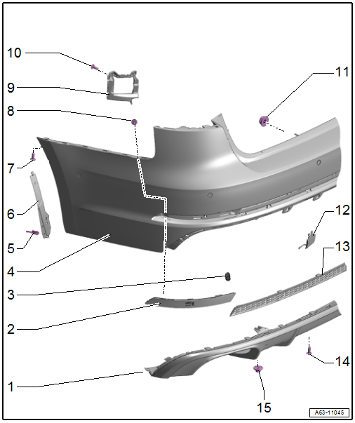
Overview - Bumper Cover
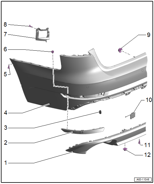
1 - Bumper Cover Lower Section
- There are different versions. Refer to the Parts Catalog.
- Removing and installing. Refer to → Chapter "Bumper Cover Lower Section, Removing and Installing".
2 - Rear Reflector
- Removing and installing. Refer to → Chapter "Reflector, Removing and Installing".
3 - Spring
- For rear reflector
4 - Rear Bumper Cover
- Removing and installing. Refer to → Chapter "Bumper Cover, Removing and Installing".
5 - Bolt
- 2 Nm
6 - Bolt
- 2 Nm
7 - Mount
- For lane change assistance control module
8 - Bolt
- 2 Nm
- Quantity: 3
9 - Nut
- 4 Nm
- Quantity: 4
10 - Cover
- For the towing eye
11 - Bolt
- 2 Nm
- Quantity: 2
12 - Nut
- 2 Nm
- Quantity: 2
Overview - Bumper Cover Mount
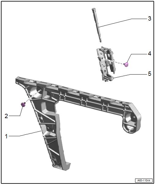
1 - Mount
- Side
- For the bumper cover
- Removing and installing. Refer to → Chapter "Bumper Cover Mount, Removing and Installing, Side".
2 - Bolt
- Quantity: 3
- Tightening sequence. Refer to → Fig. "Bumper Cover Side Mount - Tightening Specification and Sequence".
3 - Locking Mechanism
- For attaching the rear bumper cover to the upper mount
4 - Bolt
- Quantity: 2
- Tightening sequence. Refer to → Fig. "Bumper Cover Upper Mount - Tightening Specification and Sequence".
5 - Upper Mount
- Upper
- For securing the bumper cover
- Removing and installing. Refer to → Chapter "Bumper Cover Mount, Removing and Installing, Upper".
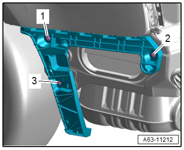
Bumper Cover Side Mount - Tightening Specification and Sequence
- Tighten the screws -1, 2 and 3- to 3 Nm.
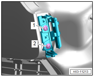
Bumper Cover Upper Mount - Tightening Specification and Sequence
- Tighten the screws -1 and 2- to 3 Nm.
Overview - Bumper Cover, S Line
Overview - Bumper Cover
1 - Bumper Cover Lower Section
- There are different versions. Refer to the Parts Catalog.
- Removing and installing. Refer to → Chapter "Bumper Cover Lower Section, Removing and Installing".
2 - Rear Reflector
- Removing and installing. Refer to → Chapter "Reflector, Removing and Installing".
3 - Spring
- For rear reflector
4 - Rear Bumper Cover
- Removing and installing. Refer to → Chapter "Bumper Cover, Removing and Installing".
5 - Expanding Rivet
- Quantity: 2
6 - Intermediate Piece
- For securing the wheel housing liner
7 - Bolt
- 2 Nm
8 - Bolt
- 2 Nm
9 - Mount
- for lane change assistance control module
10 - Bolt
- 2 Nm
- Quantity: 3
11 - Nut
- 4 Nm
- Quantity: 4
12 - Cover
- For the towing eye
13 - Trim
- For the bumper cover
- Removing and installing. Refer to → Chapter "Trim for Bumper Cover Lower Section, Removing and Installing".
14 - Bolt
- 2 Nm
- Quantity: 2
15 - Nut
- 2 Nm
- Quantity: 2
Overview - Bumper Cover Mount
1 - Mount
- Side
- For the bumper cover
- Removing and installing. Refer to → Chapter "Bumper Cover Mount, Removing and Installing, Side".
2 - Bolt
- Quantity: 3
- Tightening sequence. Refer to → Fig. "Bumper Cover Side Mount - Tightening Specification and Sequence".
3 - Locking Mechanism
- For attaching the rear bumper cover to the upper mount
4 - Bolt
- Quantity: 2
- Tightening sequence. Refer to → Fig. "Bumper Cover Upper Mount - Tightening Specification and Sequence".
5 - Upper Mount
- Upper
- For securing the bumper cover
- Removing and installing. Refer to → Chapter "Bumper Cover Mount, Removing and Installing, Upper".
Bumper Cover Side Mount - Tightening Specification and Sequence
- Tighten the screws -1, 2 and 3- to 3 Nm.
Bumper Cover Upper Mount - Tightening Specification and Sequence
- Tighten the screws -1 and 2- to 3 Nm.
Overview - Impact Member
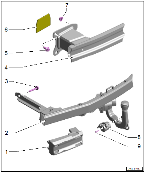
1 - Filler Piece
2 - Impact Member
- For vehicles with a trailer hitch
- Removing and installing. Refer to → Chapter "Impact Member, Removing and Installing, Vehicles with Trailer Hitch".
3 - Bolt
- 60 Nm +90º
- Replace after removing
- Quantity: 4
4 - Impact Member
- For vehicles without a trailer hitch
- Removing and installing. Refer to → Chapter "Impact Member, Removing and Installing, Vehicles without Trailer Hitch".
5 - Bolt
- Replace after removing
- Quantity: 3
- Tightening specification. Refer to → Fig. "Impact Member - Tightening Specification and Sequence".
6 - Foam Seal
7 - Nut
- Tightening specification. Refer to → Fig. "Impact Member - Tightening Specification and Sequence".
8 - Socket
- Removing and installing. Refer to → Electrical Equipment; Rep. Gr.96; Trailer Hitch; Trailer Socket.
9 - Bolt
- 3.5 Nm
- Quantity: 2
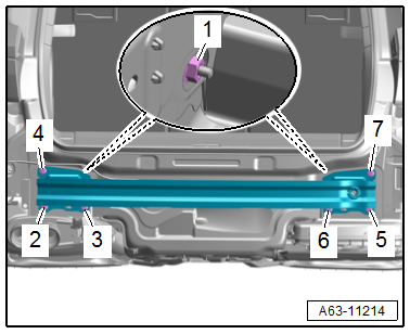
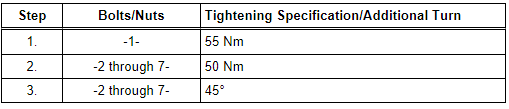
Impact Member - Tightening Specification and Sequence
- Tighten the bolts and nuts gradually in the sequence shown.
READ NEXT:
 Rear Bumper Cover, Removing and Installing
Special tools and workshop equipment
required
Body Socket -T40078-
Depending on the equipment version, the following additional work must be
performed.
Removing
- Remove the bolts -1-.
-&nb
Rear Bumper Cover Mount, Removing and Installing
Bumper Cover Mount, Removing and Installing, Upper
Removing
- Remove the rear bumper cover. Refer to
→ Chapter "Bumper Cover, Removing and Installing".
- Remove the bolts -arrows-.
-
SEE MORE:
Effects Speaker, Removing and Installing
Left and Right Effects Speaker -R209-/-R210-, Removing and Installing,
Sedan
Special tools and workshop equipment required
Trim Removal Wedge -3409-
The Left Effects Speaker -R209-/Right Effects Speaker -R210-
are located in the rear shelf.
Removing and installing is identical.
Removing
-
Brakes
General information
You can apply the vehicle's brakes using the brake
pedal.
Operating noise
Noises may occur when braking depending on the
speed, braking force, and outside conditions such
as temperature and humidity.
Braking effect
The response time from the brakes depends on
the weather and envi
