Audi A4: Lock Carrier
Overview - Lock Carrier
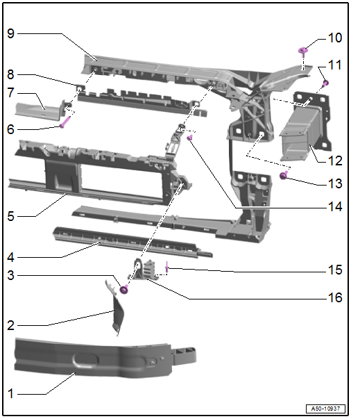
1 - Impact Member
2 - Air Duct
- Clipped into the bumper cover bracket
3 - Bolt
- 8 Nm
4 - Lower Air Guide
- For the radiator
5 - Bumper Cover Bracket
- Removing and installing. Refer to → Chapter "Bumper Cover Bracket, Removing and Installing".
6 - Bolt
- Tightening specification. Refer to → Engine Mechanical; Rep. Gr.23; Air Filter; Overview - Air Filter Housing or → Engine Mechanical; Rep. Gr.24; Air Filter; Overview - Air Filter Housing.
7 - Air Duct
- For the air filter housing
- Clean off any salt and dirt
8 - Upper Air Duct
- For the radiator
9 - Lock Carrier
- Removing and installing. Refer to → Chapter "Lock Carrier, Removing and Installing".
10 - Bolt
- 10 Nm
11 - Bolt
- 14 Nm
- Quantity: 2
12 - Mount
- For impact member
13 - Bolt
- Tightening specification -Item 6-
14 - Bolt
- 5 Nm
15 - Pop Rivet
- Quantity: 2
16 - Spring Element
- There are different versions. Refer to the Parts Catalog.
- For the bumper cover bracket
- Removing and installing. Refer to → Chapter "Spring Element for Bumper Cover Bracket, Removing and Installing".
- Adjusting. Refer to → Chapter "Height, Adjusting using Spring Element".
Lock Carrier, Removing and Installing
Special tools and workshop equipment required
- Engine Bung Set -VAS6122-
- Follow the safety precautions. Refer to → Body Interior; Rep. Gr.00; Safety Precautions; Safety Precautions when Working on Pyrotechnic Components.
- To complete the procedure, a second technician is required to be at the following position.
Removing
- Remove the noise insulation. Refer to → Chapter "Noise Insulation, Removing and Installing, Front".
- Remove the front bumper cover. Refer to → Chapter "Bumper Cover, Removing and Installing".
- Remove the bumper cover mount. Refer to → Chapter "Bumper Cover Mount, Removing and Installing".
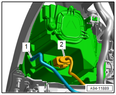
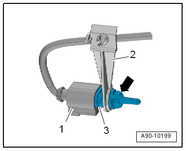
- Disconnect the connector -2-.
- Remove the breather hose -1-.
- Remove the bolts -arrows- and then remove the air guides -1 and 2-.
- On the left: release the retainers -arrow- and remove the air guide -3-.
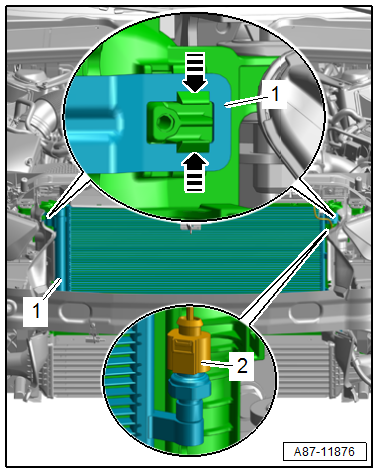
- Disconnect the connector -2- for the High Pressure Sensor -G65-.
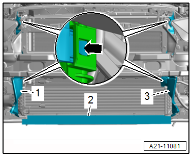
 NOTICE
Risk of destroying the refrigerant lines by tearing the inner film.
- Never bend refrigerant lines with a radius less than 100 mm (3.93 in.).
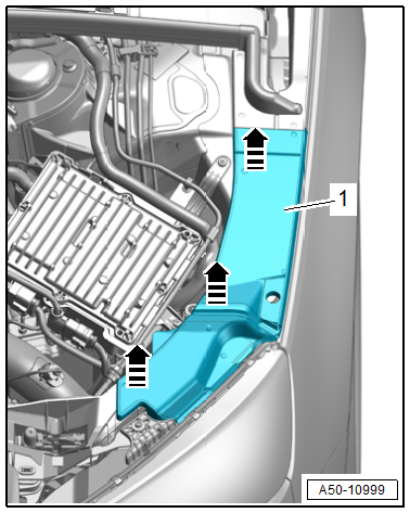
- Release the left and right catches in the direction of -arrows- disengage the condenser -1- from the radiator and tie up to the side.
 CAUTION
Pyrotechnic components may deploy unintentionally.
Risk of injury.
- Discharge static electricity by briefly touching the door striker.
- Vehicles with pedestrian protection: Disconnect the connector -1- from the pedestrian protection crash sensor and free up the wiring harness -2-.
- If required, remove the air filter housing. For TDI vehicles, refer to → Engine Mechanical; Rep. Gr.23; Air Filter; Air Filter Housing, Removing and Installing. For TFSI vehicles, refer to → Engine Mechanical; Rep. Gr.24; Air Filter; Air Filter Housing, Removing and Installing.
- If equipped, release the retainer in the direction of -arrow-, remove the NOx Sensor Control Module -J583--3- and free it up.
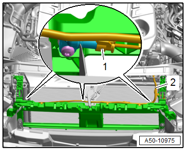
- Disconnect the latch release cable at the coupling and free it up at the lock carrier. Refer to → Chapter "Overview - Release Cable".
- Disconnect the connector -2-.
- Disconnect the connector -1- from the pedestrian protection crash sensor and free up the wiring harness.
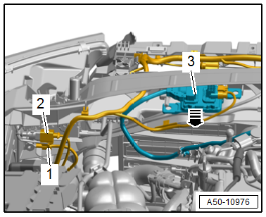
- Disconnect the connector -1- and free up the wiring harness.
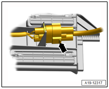
- If equipped, place the drip tray under the separating point and disconnect the washer fluid hose -3- by pressing the release buttons in the direction of -arrows-.
- Free up the washer fluid hose -4-.
- Disconnect the connector -2- from the pedestrian protection crash sensor.
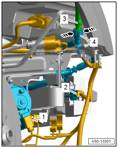
- Disconnect the connector -1- from the Outside Air Temperature Sensor -G17--3- and free up the wiring harness.
- Drain the coolant. Refer to → Engine Mechanical; Rep. Gr.19; Cooling System/Coolant; Coolant, Draining and Filling.
- Remove the coolant hoses from the radiator. Refer to → Engine Mechanical; Rep. Gr.19; Radiator/Radiator Fan; Radiator, Removing and Installing.
- Versions with charge air cooler (air flows through): Remove the air duct pipe from the charge air cooler. Refer to → Engine Mechanical; Rep. Gr.21; Charge Air System; Charge Air Cooler, Removing and Installing.
- Equipped on some models with charge air cooling circuit cooler (water flows through): Remove and free up the coolant hoses from the charge air cooling circuit cooler. Refer to → 4-Cylinder Direct Injection 1.4L 4V TFSI Engine (EA 211); Rep. Gr.19; Radiator/Radiator Fan; Charge Air Cooling Circuit Cooler, Removing and Installing.
- Disconnect the radiator fan connector -arrow-.
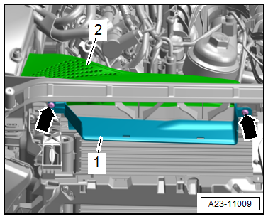
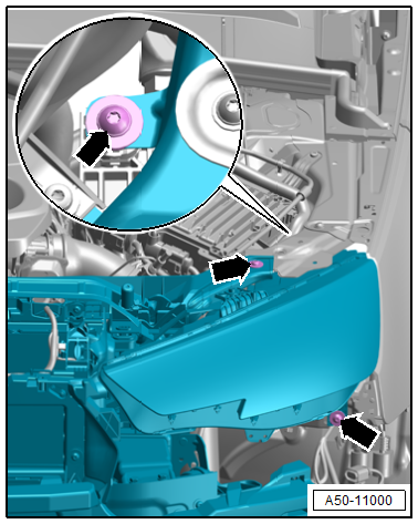
- If equipped, pry off the cover -1--arrows-.
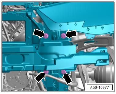
- Remove the bolts -arrows-.
- Have a second technician hold the lock carrier and remove the bolts -arrows-.
- Remove the lock carrier with a second technician.
- The following components must also be removed if the lock carrier is being replaced:
- Radiator. Refer to → Engine Mechanical; Rep. Gr.19; Radiator/Radiator Fan; Radiator, Removing and Installing.
- Charge air cooler (air flowing through). Refer to → Engine Mechanical; Rep. Gr.21; Charge Air System; Charge Air Cooler, Removing and Installing.
- Charge air cooling circuit cooler (water flows through). Refer to → 4-Cylinder Direct Injection 1.4L 4V TFSI Engine (EA 211); Rep. Gr.19; Radiator/Radiator Fan; Charge Air Cooling Circuit Cooler, Removing and Installing.
- Headlamps. Refer to → Electrical Equipment; Rep. Gr.94; Headlamps; Headlamps, Removing and Installing.
- Impact Member. Refer to → Chapter "Impact Member, Removing and Installing".
- Latch. Refer to → Chapter "Latch, Removing and Installing".
Installing
Install in reverse order of removal and note the following:
- Fill with coolant. Refer to → Engine Mechanical; Rep. Gr.19; Cooling System/Coolant; Coolant, Draining and Filling.
Tightening Specifications
- Refer to → Chapter "Overview - Lock Carrier"
READ NEXT:
 Bumper Cover Bracket, Removing and Installing
Follow the safety precautions. Refer to
→ Body Interior; Rep. Gr.00; Safety Precautions; Safety
Precautions when Working on Pyrotechnic Components.
Removing
- Remove the impa
Fender
Overview - Fender
1 -
Nut
8 Nm
2 -
Outer Fender Brace
Removing and installing. Refer to
→ Chapter "Brace and Outer Fender Brace, Removing and Installing".
3 -&n
Fender, Removing and Installing
Special tools and workshop equipment
required
Pop Rivet Nut Pliers -VAS5072A-
Drill
Pop rivets. Refer to the Parts Catalog.
Follow the safety precautions. Refer to
→ Body Interior; Re
SEE MORE:
Audi pre sense
Function overview
Applies to: vehicles with Audi pre sense
Within the limits of the system, the Audi pre
sense functions can initiate measures in certain
driving situations to protect the vehicle occupants
and other road users. Depending on the vehicle
equipment, various Audi pre sense systems
may b
Opening navigation
Applies to: vehicles with navigation system
Fig. 140 Route guidance not started
The navigation system directs you to your destination,
around traffic incidents, and on alternative
routes, if desired.
Opening navigation
Applies to: MMI: Press NAVIGATION on the
home screen.
After accessing the na
