Audi A4: Seat Position Sensor
Overview - Seat Position Sensor
 Note
Note
The front passenger side is shown.
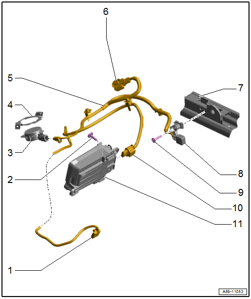
1 - Connector Coupling
- Connector station in the underbody under the seat.
2 - Bolt
- 1.2 Nm
3 - Front Passenger Occupant Detection Sensor -G128-
- Only the front passenger side
- Removing and installing. Refer to → Chapter "Front Passenger Occupant Detection Sensor -G128-, Removing and Installing".
- Push the clips into the seat pan until they click into place.
4 - Passenger Occupant Detection Sensor Bracket
- Clipped in the seat frame.
- Removing and installing. Refer to → Chapter "Front Passenger Occupant Detection Sensor -G128-, Removing and Installing".
5 - Wiring Harness
- Clipped in the seat frame.
6 - Connector Coupling
- For the seat belt latch
7 - Seat Rail
- Tunnel-side
8 - Seat Position Sensor
- Driver Seat Position Sensor -G553-
- Front Passenger Seat Position Sensor -G554-
- Removing and installing. Refer to → Chapter "Seat Position Sensor, Removing and Installing".
9 - Bolt
- 1.6 Nm
10 - Connector Coupling
- For the Passenger Occupant Detection System Control Module -J706-
- Only the front passenger side
11 - Passenger Occupant Detection System Control Module -J706-
- Market-Specific Version
 Caution
Risk of malfunction.
Never disconnect the connector between the Front Passenger Occupant Detection Sensor -G128- and the Passenger Occupant Detection System Control Module -J706-.
- Clipped in the storage compartment.
Seat Position Sensor, Removing and Installing
The seat position sensor is available as a replacement part with the wiring harness and connector. The following wires with connectors are contained in the wiring harness:
- Driver Seat Position Sensor -G553-: wire with connector for seat belt latch connection.
- Front Passenger Seat Position Sensor -G554-: wire with connector for seat belt latch connection, passenger occupant detection sensor and passenger occupant detection system control module (market-specific).
Removing
- Disconnect the modular wiring routing. Refer to → Chapter "Modular Wiring Routing, Disconnecting and Connecting".
- Open the corrugated tube, remove the wire for the Driver Seat Position Sensor -G553-/ Front Passenger Seat Position Sensor -G554- with the connector and free up.
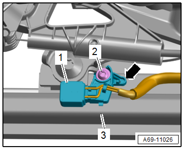
- Remove the bolt -2-.
- Unclip and disengage the seat position sensor -1- for the seat pan lower frame -3--arrow-.
- Remove the cable ties or cable clips for the wire on the seat pan lower frame.
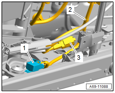
Driver Seat
- Free up the connector -3- for the seat belt latch and disconnect.
- Remove the seat position sensor -1- with the wire -2-.
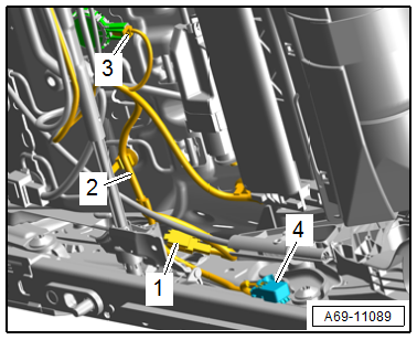
Front Passenger Seat
- Free up the connector -1- for the seat belt latch and disconnect.
- Disconnect the connector -3- on the Front Passenger Occupant Detection Sensor -G128-.
- Remove the seat position sensor -4- with the wire -2-.
Installing
Install in reverse order of removal.
Installation instructions: For example tightening specifications, replacing components. Refer to → Chapter "Overview - Seat Position Sensor".
READ NEXT:
 Belt Fastening Detection
Front Passenger Occupant Detection Sensor -G128-, Removing and Installing
Note
The passenger occupant detection sensor is only installed in the
front passenger seat.
Removing
- Unscrew t
Pedestrian Protection
Overview - Pedestrian Protection
1 - Driver Side Pedestrian Protection Crash Sensor 2 -G851-/Front Passenger
Side Pedestrian Protection Crash Sensor 2 -G852-
Unit with pressure hose
Com
SEE MORE:
Head-up display
Description
Applies to: vehicles with head-up display
Fig. 19 Instrument panel: knob for the head-up display
The head-up display projects certain warnings or
selected information from the assist systems on
the windshield. The display appears within the
driver's field of vision.
Switching on and off
Battery Tester -VAS6161-
General Description:
WARNING
Risk of injury. Follow all warning messages and
safety precautions. Refer to
→ Chapter "Warnings and Safety Precautions".
It is not necessary to disconnect or remove the Battery -A-
when using the Battery Tester -VAS6161-.
The Battery Tester -VAS6161-
