Audi A4: Subframe Mount
Overview - Subframe Mount
Engine Mount
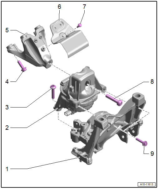
1 - Subframe
2 - Engine Mount
- Versions with
- Left Electrohydraulic Engine Mount Solenoid Valve -N144-
- Right Electrohydraulic Engine Mount Solenoid Valve -N145-
- Removing and installing. Refer to → Chapter "Engine Mount, Removing and Installing".
3 - Bolt
- 55 Nm
4 - Bolt
- 55 Nm
5 - Engine Support
6 - Heat Shield
7 - Bolt
- 10 Nm
8 - Bolt
- 90 Nm + 90º
- Replace after removing
9 - Bolt
- 30 Nm
Manual Transmission Mount
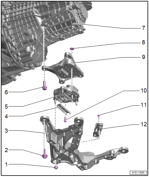
1 - Nut
- Only remove when the transmission mount must be separated from the transmission support
- Tightening specifications. Refer to → Manual Transmission; Rep. Gr.34; Subframe; Overview - Subframe.
2 - Bolt
- Tightening specifications. Refer to → Manual Transmission; Rep. Gr.34; Subframe; Overview - Subframe.
3 - Tunnel Crossmember
- Removing and installing. Refer to → Manual Transmission; Rep. Gr.34; Subframe Mount; Overview - Subframe Mount.
4 - Stop
- For the transmission mount
5 - Transmission Mount
- Removing and installing. Refer to → Chapter "Transmission Mount, Removing and Installing".
6 - Bolt
- Tightening specifications. Refer to → Manual Transmission; Rep. Gr.34; Subframe; Overview - Subframe.
7 - Transmission
8 - Nut
- Only remove when the transmission mount must be separated from the transmission support
- Tightening specifications. Refer to → Manual Transmission; Rep. Gr.34; Subframe; Overview - Subframe.
9 - Transmission Support
- Removing and installing. Refer to → Chapter "Transmission Mount, Removing and Installing".
10 - Bolt
- Tightening specifications. Refer to → Manual Transmission; Rep. Gr.34; Subframe; Overview - Subframe.
11 - Bolt
- 9 Nm
12 - Bracket
- For the connector
Dual-Clutch Transmission Mount
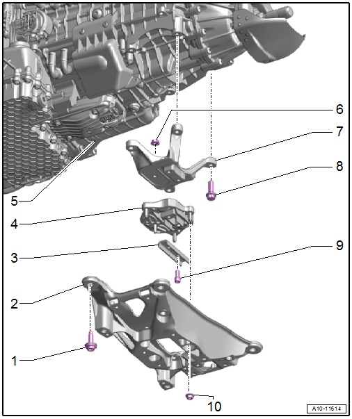
1 - Bolt
- Tightening specifications. Refer to → S tronic Transmission; Rep. Gr.34; Subframe Mount; Overview - Subframe Mount.
2 - Tunnel Crossmember
- Removing and installing. Refer to → S tronic Transmission; Rep. Gr.34; Subframe Mount; Overview - Subframe Mount.
3 - Stop
- For the transmission mount
4 - Transmission Mount
- Removing and installing. Refer to → Chapter "Transmission Mount, Removing and Installing".
5 - Transmission
6 - Nut
- Only remove when the transmission mount must be separated from the transmission support
- Tightening specifications. Refer to → S tronic Transmission; Rep. Gr.34; Subframe Mount; Overview - Subframe Mount.
7 - Transmission Support
- Removing and installing. Refer to → Chapter "Transmission Mount, Removing and Installing".
8 - Bolt
- Tightening specifications. Refer to → S tronic Transmission; Rep. Gr.34; Subframe Mount; Overview - Subframe Mount.
9 - Bolt
- Only remove when the transmission mount must be separated from the transmission support
- Tightening specifications. Refer to → S tronic Transmission; Rep. Gr.34; Subframe Mount; Overview - Subframe Mount.
10 - Nut
- Only remove when the transmission mount must be separated from the transmission support
- Tightening specifications. Refer to → S tronic Transmission; Rep. Gr.34; Subframe Mount; Overview - Subframe Mount.
READ NEXT:
 Engine, Supporting in Installation Position
Special tools and workshop equipment required
Engine Support Bridge -10-222A-
Procedure
- Remove the engine cover. Refer to
→ Servicing - 4-Cylinder 2.0L 4V TFSI Engine; Rep. Gr.1
Special Tools
Special tools and workshop equipment required
Locking Pin -T10060A-
Engine Support - Supplement Kit - Adapter -T40093/6- from
the Engine Support - Supplement Kit -T40093A-
Clutch Module Ass
SEE MORE:
Coolant System/Coolant
Connection Diagram - Coolant Hoses
Connection Diagram - Coolant Hoses, Versions without Parking Heater
Note
Blue = large coolant circuit.
Red = small coolant circuit.
Brown = heating circuit.
Green = coolant circuit for the transmission.
The arrows show the coolant flow direction.
1&
Luggage Compartment Trim Panels
Component Location Overview - Luggage Compartment Trim Panels
Component Location Overview - Luggage Compartment Trim Panels, Sedan
1 - Lock Carrier Trim
Overview. Refer to
→ Chapter "Overview - Luggage Compartment Side Trim Panel, Sedan".
2 - Luggage Compartment Side
© 2019-2026 Copyright www.audia4b9.com
