Audi A4: Engine, Supporting in Installation Position
Special tools and workshop equipment required
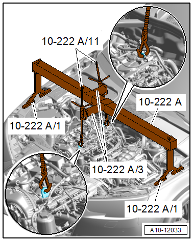
- Engine Support Bridge -10-222A-
Procedure
- Remove the engine cover. Refer to → Servicing - 4-Cylinder 2.0L 4V TFSI Engine; Rep. Gr.10; Engine Cover; Engine Cover, Removing and Installing.
- Position the -10-222A- as shown on the left and right fender bolting edges.
- Engage the -10-222A/11- on the engine lifting eye.
- Pretension the engine with the spindle, do not lift.
Assembling
Assembly is performed in reverse order.
Engine Mount, Removing and Installing
 Caution
This procedure contains mandatory replaceable parts. Refer to component overview and parts catalog prior to starting procedure.
Mandatory Replacement Parts
- Bolt - Engine Mount to Engine Support
Removing
- Remove the front noise insulation. Refer to → Body Exterior; Rep. Gr.66; Noise Insulation; Overview - Noise Insulation.
- Remove the front wheel spoiler. Refer to → Body Exterior; Rep. Gr.66; Wheel Housing Liner; Front Wheel Housing Liner, Removing and Installing.
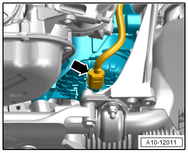
- Disconnect the connector -arrow- for the electrohydraulic engine mount solenoid valves.
Right Engine Mount
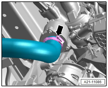
- Loosen the hose clamp -arrow- and remove the air duct hose.
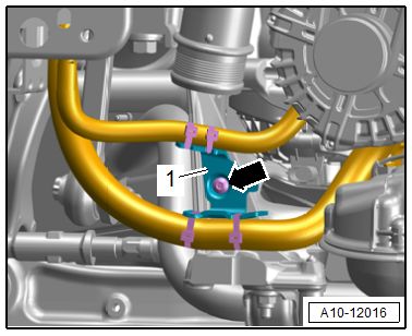
- Remove the nut -arrow- and free up the ground wire.
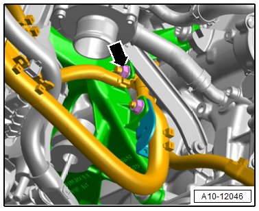
- Remove the bolt -arrow- and free up the bracket -1- with the wiring harness.
Continuation for Both Sides
Caution
Risk of damaging the drive axles.
When lifting the engine the drive axles must not come into contact with the suspension struts.
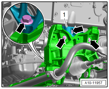
- Support the engine in the installation position. Refer to → Chapter "Engine, Supporting in Installation Position" and tension with the -10-22A/11- until the engine mount is engaged.
- Remove the bolts -arrows- and engine mount -1-.
Installing
Install in reverse order of removal and note the following:
 Note
Note
Replace the bolts that were tightened with an additional turn after removing them.
- Connections and wire routing. Refer to → Wiring diagrams, Troubleshooting & Component locations.
Tightening Specifications
- Refer to → Chapter "Overview - Subframe Mount"
- Refer to → Servicing - 4-Cylinder 2.0L 4V TFSI Engine; Rep. Gr.21; Charge Air System; Overview - Charge Air Hose Connections.
- Refer to → Body Exterior; Rep. Gr.66; Wheel Housing Liner; Overview - Front Wheel Housing Liner.
- Refer to → Body Exterior; Rep. Gr.66; Noise Insulation; Overview - Noise Insulation.
Transmission Mount, Removing and Installing
Transmission Support with Transmission Mount, Removing and Installing
Removing
- Remove the tunnel crossmember. Refer to → Manual Transmission; Rep. Gr.34; Subframe; Overview - Subframe or → Direct Shift Gearbox; Rep. Gr.34; Subframe; Overview - Subframe.
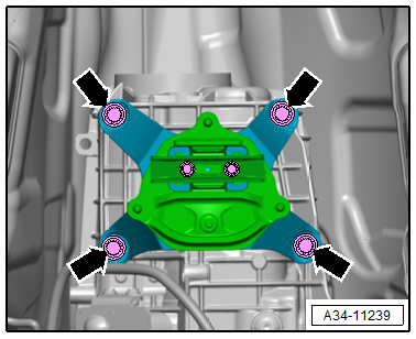
- Remove the bolts -arrows- and remove the transmission support with the transmission mount from the transmission.
Installing
Install in reverse order of removal.
Tightening Specifications
- Refer to → Manual Transmission; Rep. Gr.34; Subframe; Overview - Subframe.
- Refer to → Direct Shift Gearbox; Rep. Gr.34; Subframe Mount; Overview - Subframe Mount.
Transmission Mount, Removing and Installing
Removing
- Remove the transmission support with the transmission mount. Refer to → Chapter "Transmission Support with Transmission Mount, Removing and Installing".
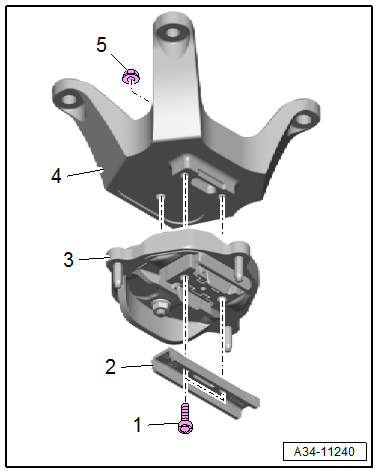
- Remove the bolts -1- and remove the stop -2- for the transmission mount.
- Remove the nut -5- and remove the transmission mount -3- from the transmission support -4-.
Installing
Install in reverse order of removal and note the following:
- Tighten the nut -5- hand-tight.
- Tighten the bolts -1- and then the nut -5-.
- Install the transmission support with the transmission mount. Refer to → Chapter "Transmission Support with Transmission Mount, Removing and Installing".
Tightening Specifications
- Refer to → Manual Transmission; Rep. Gr.34; Subframe; Overview - Subframe.
- Refer to → Direct Shift Gearbox; Rep. Gr.34; Subframe Mount; Overview - Subframe Mount.
Engine Cover
Refer to → Servicing - 4-Cylinder 2.0L 4V TFSI Engine; Rep. Gr.10; Engine Cover.
READ NEXT:
 Special Tools
Special tools and workshop equipment required
Locking Pin -T10060A-
Engine Support - Supplement Kit - Adapter -T40093/6- from
the Engine Support - Supplement Kit -T40093A-
Clutch Module Ass
Cylinder Block, Belt Pulley Side
Overview - Cylinder Block, Belt Pulley Side
All components are described under:
→ Servicing - 4-Cylinder 2.0L 4V TFSI Engine; Rep. Gr.13; Cylinder Block Belt
Pulley Side; Overview -
SEE MORE:
Condenser
The condenser conducts heat from compressed refrigerant gas
to the ambient air.
This condenses the refrigerant gas to fluid.
Note
Depending on the version of the refrigerant circuit, the
receiver/dryer is installed (integrated) either on the condenser
or inside the condenser. Refer to
Global functions
Additional function buttons
Fig. 21 Right side of the multifunction steering wheel
Fig. 22 MMI On/Off knob with joystick function
Adjusting the volume
You can adjust the volume of an audio source or a
system message (for example, from the voice
recognition system) when the sound is playing.
To i
