Audi A4: Wheel Bearing Unit, Removing and Installing
Special tools and workshop equipment required
- Torque Wrench 1332 40-200Nm -VAG1332-
 Caution
This procedure contains mandatory replaceable parts. Refer to component overview and parts catalog prior to starting procedure.
Mandatory Replacement Parts
- Bolt - Ball Joint to Wheel Bearing Housing
- Nut - Ball Joint to Control Arm
Removing
Caution
There is a risk of damaging or contaminating the wheel bearing.
Handling the wheel bearing.
- Loosen the connection between the drive axle and wheel hub. Refer to → Chapter "Drive Axle Threaded Connection, Loosening and Tightening".
- Remove the brake rotor. Refer to → Brake System; Rep. Gr.46; Front Brakes; Brake Rotor, Removing and Installing.
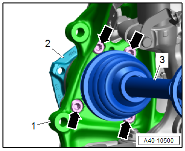
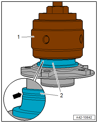
- Remove the bolts -arrows-.
- Remove the wheel hub -2- with the wheel bearing unit from the drive axle -3- and remove it from the wheel bearing housing -1-.
Installing
Install in reverse order of removal and note the following:
- Tighten the threaded connection between the drive axle and wheel hub. Refer to → Chapter "Drive Axle Threaded Connection, Loosening and Tightening".
Tightening Specifications
- Refer to → Chapter "Overview - Wheel Bearing"
- Refer to → Chapter "Wheels and Tires"
Wheel Bearing Unit, Servicing
Special tools and workshop equipment required
- Press Plate -VW401-
- Press Plate -VW402-
- Press Piece - Multiple Use -VW412-
- Hydraulic Press - Bushing Assembly Tool Kit -T10230-
- Pneumatic Hydraulic Press -VAS6654-
- Puller Set VAS701 003 -VAS70003-
- Hydraulic Press - Bushing Assembly Tool Kit - Sleeve -T10230/3-
- Hydraulic Press - Bushing Assembly Tool Kit - Thrust Piece -T10230/8-
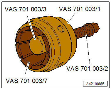
- Puller Set VAS701 003 -VAS701003-
- Puller Set - Clamping Sleeve -VAS701003/1-
- Puller Set - Threaded Spindle -VAS701003/2-
- Puller Set - Thrust Piece -VAS701003/3-
- Puller Set - Clamping Handle -VAS70003/4-
- Puller Set - Special Ring Spanner AF36 -VAS701003/5-
- Puller Set - Clamping Pliers, Diameter 66-70 mm -VAS701003/7-
Procedure
- Wheel bearing unit is removed. Refer to → Chapter "Wheel Bearing Unit, Removing and Installing".
Wheel Hub, Removing from Wheel Bearing
- Arrange the special tools as shown.
1 - -VW412-
2 - -T10230/3-
3 - -T10230/8-
4 - Wheel Bearing Unit
5 - -VW402-
6 - -VW401-
- Press the wheel hub out of the wheel bearing.
Bearing Inner Race, Removing from Wheel Hub
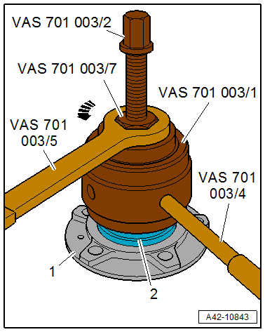
- Prepare the puller from the -VAS701003- as follows:
- Install the -VAS701003/1- on the -VAS701003/7-.
- Install the -VAS701003/2- in the adapter sleeve and attach the -VAS701003/3-.
Bearing Inner Race Version 1
- Remove the ball-cage assembly from the bearing inner race -2-.
- Place the puller -1- as shown on the ball bearing race -arrow- of the bearing inner race.
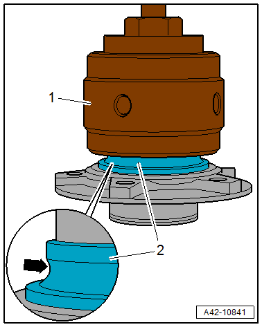
Bearing Inner Race Version 2
- Place the puller -1- on the groove -arrow- of the bearing inner race -2-.
Continuation for All Versions
- Clamp the puller on the bearing inner race -2- by turning the -VAS701003/7- with the -VAS701003/5- in the direction of the -arrow- and counterhold the -VAS701 003/1- with the -VAS70003/4-.
- Remove the bearing inner race with the - VAS701003/2- from the wheel hub -1-.
Wheel Hub, Pressing in Wheel Bearing
Handling the wheel bearing. Refer to → Fig. "Wheel Bearing, Handling".
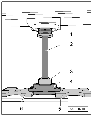
- Arrange the special tools as shown.
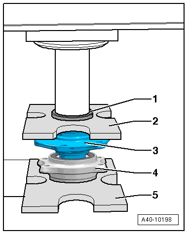
1 - -VW412-
2 - -VW402-
3 - Wheel Hub
4 - Wheel Bearing
5 - -VW401-
- The reworked surface of the wheel bearing outer race faces down.
Caution
There is a risk of damaging or contaminating the wheel bearing.
When setting down or pressing in, make sure there is no dirt or contaminants between the -VW401- and the wheel bearing.
- Press the wheel hub into the wheel bearing.
- Install the wheel bearing unit. Refer to → Chapter "Wheel Bearing Unit, Removing and Installing".
READ NEXT:
 Overview - Drive Axle
1 - Clamp
Replace after removing
Tensioning. Refer to
→ Chapter "Clamp on Triple Roller Joint and Outer Joint, Tensioning".
2 - CV Boot
If the drive axle has a peene
Drive Axle, Removing and Installing
Special tools and workshop equipment required
Torque Wrench 1332 40-200Nm -VAG1332-
Caution
This procedure contains mandatory replaceable parts.
Refer to component overview and parts cata
SEE MORE:
Service Station, Connecting with No Connection on Low- and High Pressure
Side of Refrigerant Circuit
General Information
On the following vehicles, no service connection is provided
for the service station on the low-pressure side of the
refrigerant circuit; adapters must be used to connect the
service station to the refrigerant circuit on these vehicles:
Audi 80, Audi Cabrio, Audi Coupe
Audi
Lap timer
Introduction
Applies to: vehicles with lap timer
You can record and evaluate lap times with the
lap timer. You can operate the lap timer using the
multifunction steering wheel.
Opening the lap timer
Select in the instrument cluster: Vehicle functions
tab > button > Lap times.
An additiona
