Audi A4: Air Intake Grille, Removing and Installing
Air Intake Grille, Removing and Installing, Center
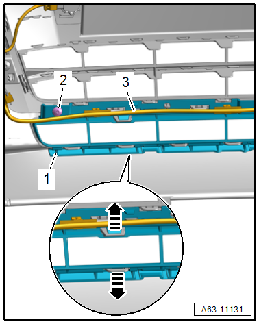
Removing
- Remove the front bumper cover end plate. Refer to → Chapter "Front Bumper Cover End Plate, Removing and Installing".
- Free up the wiring harness -3-.
- Remove the bolts -2-.
- Release the retainers in the direction of -arrows- and remove the air intake grille -1- from the bumper cover.
Installing
Install in reverse order of removal and note the following:
- Place the air intake grille on the bumper cover and push it on. While doing so, the catches must fully engage in the bumper cover.
Air Intake Grille, Removing and Installing, Side
Special tools and workshop equipment required
- Removal Wedge -T40233-
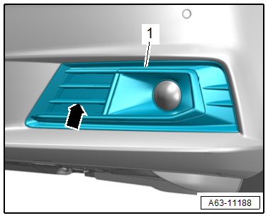
Air Intake Grille, Removing and Installing, Standard Equipment
Removing
- Grasp the recessed handle -arrow- and pull the air intake grille -1- at the inner side out of the bumper cover.
Installing
Install in reverse order of removal.
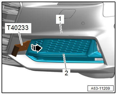
Air Intake Grille, Removing and Installing, S Line
Removing
- Slide the -T40233- between the bumper cover -1- and air intake grille -2-.
- Release the air intake grille -arrow- and remove it from the bumper cover.
Installing
Install in reverse order of removal.
READ NEXT:
 Impact Member, Removing and Installing
Follow the safety precautions. Refer to
→ Body Interior; Rep. Gr.00; Safety Precautions; Safety
Precautions when Working on Pyrotechnic Components.
- Remove the bumper cover.
Attachments, Removing and Installing
Lock Carrier Cover, Removing and Installing
Special tools and workshop equipment
required
Removal Wedge -T40233-
Removing
- Remove the hook release lever. Refer to
→ Chapter "Hook Rele
Rear Bumper
Overview - Rear Bumper Cover, Standard Equipment
Overview - Bumper Cover
1 -
Bumper Cover Lower Section
There are different versions. Refer to the Parts Catalog.
Removing and installing.
SEE MORE:
Speaker Trim in Door Trim Panels, Removing and Installing
Special tools and workshop equipment required
Pry Lever -80-200-
Front Bass Speaker Trim, Removing
- Carefully pry out the speaker trim -1-
along the door trim panel seam using the Pry Lever -80-200- in
the direction of -arrow A-.
- Disengage the speaker trim at the rear from the door
Rear Thorax Airbag with Igniter, Removing and Installing
Caution
This procedure contains mandatory replaceable parts.
Refer to component overview and parts catalog prior to
starting procedure.
Mandatory Replacement Parts
Nut - Rear Thorax Airbag to Side Cushion
Removing
WARNING
Risk of injury due to involuntary deployment.
Pay att
