Audi A4: Airbag Adapter, Connecting and Disconnecting
Special tools and workshop equipment required
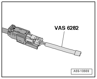
- Airbag Lockout Adapter -VAS6282-
Airbag Connector, Disconnecting
- Move the front seat all the way to the rear and then into its highest position.
- Fold up the cover in the carpet.
 WARNING
Risk of injury due to involuntary deployment.
- Pay attention to the safety precautions when working with pyrotechnic components. Refer to → Chapter "Safety Precautions when Working with Pyrotechnic Components".
- Before handling pyrotechnic components (For example, disconnecting the connector), the person handling it must "discharge static electricity". For example, this can be done by briefly touching the door striker.
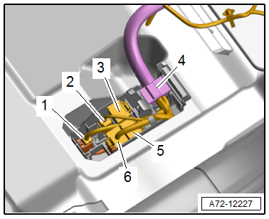
- Unclip the cable holder -4-.
- Disconnect the connector -2- for the thorax airbag from the connector station by releasing the tabs.
- If required, disconnect the remaining connectors -1, 3, 5 and 6-.
- Connect the -VAS6282- to the thorax airbag connector.
 Caution
Risk of unintended deployment due to electrostatic discharge.
The -VAS6282- must stay connected to seat until the seat is installed again.
 Note
Note
Ensure the airbag adapter engages correctly.
Airbag Connector, Connecting
WARNING
Risk of injury due to involuntary deployment.
- Pay attention to the safety precautions when working with pyrotechnic components. Refer to → Chapter "Safety Precautions when Working with Pyrotechnic Components".
- Before handling pyrotechnic components (For example, connecting a connector), the person handling it must "discharge static electricity". For example, this can be done by briefly touching the door striker.
Connecting the airbag connectors happens in reverse order, noting the following:
Note
Make sure the connectors are pushed in all the way and that they engage audibly.
WARNING
Repairing pyrotechnic components (For example the airbag and seat belt tensioner) incorrectly increases the risk of unintentional deployments when the battery is connected.
- The ignition must be on when connecting the battery.
- Make sure that no one is inside the vehicle at the time when the battery is connected.
- Connect the battery ground cable with the ignition switched on. Refer to → Electrical Equipment; Rep. Gr.27; Battery; Battery, Disconnecting and Connecting.
Note
If the Airbag Indicator Lamp -K75- indicates a fault, check the DTC memory, erase it and check it again using the Vehicle Diagnostic Tester.
Modular Wiring Routing, Disconnecting and Connecting
Special tools and workshop equipment required
- Engine/Transmission Holder - Seat Repair Fixture -VAS6136-
Individual Wire, Removing
WARNING
Risk of injury due to involuntary deployment.
- Pay attention to the safety precautions when working with pyrotechnic components. Refer to → Chapter "Safety Precautions when Working with Pyrotechnic Components".
- Before handling pyrotechnic components (For example, disconnecting the connector), the person handling it must "discharge static electricity". For example, this can be done by briefly touching the door striker.
- Remove the front seat. Refer to → Chapter "Front Seat, Removing and Installing".
- Fasten the front seat on the -VAS6136-. Refer to → Chapter "Front Seat, Mounting on Fixture for Seat Repair".
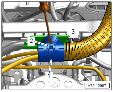
- Open the rear cable holder -1- for the wire routing on the seat pan using a screwdriver to release the hook -2-.
- Remove the corrugated tube -3- from the cable holder.
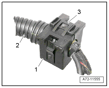
- Open the front cable holder -1- using a screwdriver to release the hook -3-.
- Remove wiring bracket from the corrugated tube -2-.
- Disconnect the halves of the corrugated tube.
- Cut the cable tie if necessary to remove a single wire.
Note
To replace a faulty wire or thorax airbag. Refer to → Electrical Equipment General Information; Rep. Gr.97; Wiring Harness and Connector Repair; Wiring Harnesses, Repairing.
- Cut through the cable tie and remove the individual wire.
Individual Wire, Installing
WARNING
Repairing pyrotechnic components (For example the airbag and seat belt tensioner) incorrectly increases the risk of unintentional deployments when the battery is connected.
- Pay attention to the safety precautions when working with pyrotechnic components. Refer to → Chapter "Safety Precautions when Working with Pyrotechnic Components".
- Before handling pyrotechnic components (For example, connecting a connector), the person handling it must "discharge static electricity". For example, this can be done by briefly touching the door striker.
- Follow all the instructions when installing the front seat. Refer to → Chapter "Front Seat, Removing and Installing".
Install in reverse order of removal and note the following:
- When bundling and placing individual wires, make sure the wires are not twisted.
Note
- During installation, all cable ties, cable holders and clips must be installed at the same location.
- Make sure the connectors are pushed in all the way and that they engage audibly.
Installation instructions: For example tightening specifications, replacing components. Refer to → Chapter "Overview - Front Seat".
READ NEXT:
 Seat Forward/Back Adjuster, Removing and Installing
Seat Forward/Back Adjuster, Removing and Installing, Seat Forward/Back
Adjustment Handle
Removing
- Unscrew the front seat and tip to the rear with the wires
attached. Refer to
→ Chapte
Backrest Adjuster, Removing and Installing
Backrest Adjustment Hand Wheel, Removing and Installing
Special tools and workshop equipment required
Assembly Tool -3399-
Removing
- Move the front seat all the way forward into its highest
Front Backrest, Removing and Installing
Front Backrest, Removing and Installing
Special tools and workshop equipment required
Engine/Transmission Holder - Seat Repair Fixture -VAS6136-
Caution
This procedure contains mandatory r
SEE MORE:
Fender
Overview - Fender
1 -
Nut
8 Nm
2 -
Outer Fender Brace
Removing and installing. Refer to
→ Chapter "Brace and Outer Fender Brace, Removing and Installing".
3 -
Bolt
8 Nm
4 -
Bolt
8 Nm
Quantity: 2
5 -
Fender Brace
Removing and in
Front Midrange Speaker, Removing and Installing
The Left Front Midrange Speaker -R103-/Right Front Midrange
Speaker -R104--1- are located in
the center of the front doors.
Removing and installing is identical.
Removing
- Turn off the ignition and all electrical equipment and
remove the ignition key.
- Remove the front door trim panel
