Audi A4: Backrest Adjuster, Removing and Installing
Backrest Adjustment Hand Wheel, Removing and Installing
Special tools and workshop equipment required
- Assembly Tool -3399-
Removing
- Move the front seat all the way forward into its highest position.
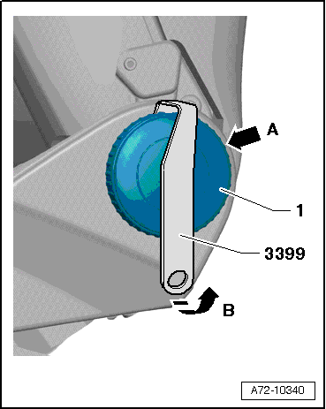
- Turn the backrest adjustment wheel -1- until one catch is visible from behind -arrow A-. If necessary use a flashlight.
- Attach the -3399- to the catch and pry off the hand wheel in the direction of -arrow B-.
- Turn the backrest adjustment hand wheel 120º farther and repeat the process.
- Remove the backrest adjustment hand wheel.
Installing
Install in reverse order of removal.
Installation instructions: For example tightening specifications, replacing components. Refer to → Chapter "Overview - Seat Pan, Trim Panels".
Driver and Front Passenger Backrest Adjustment Motor -V45-/-V46-, Removing and Installing
Special tools and workshop equipment required
- Engine/Transmission Holder - Seat Repair Fixture -VAS6136-
Removing
 WARNING
Risk of injury due to involuntary deployment.
- Pay attention to the safety precautions when working with pyrotechnic components. Refer to → Chapter "Safety Precautions when Working with Pyrotechnic Components".
- Before handling pyrotechnic components (For example, disconnecting the connector), the person handling it must "discharge static electricity". For example, this can be done by briefly touching the door striker.
- Remove the front seat. Refer to → Chapter "Front Seat, Removing and Installing".
- Fasten the front seat on the -VAS6136-. Refer to → Chapter "Front Seat, Mounting on Fixture for Seat Repair".
- Remove the tunnel-side seat side trim. Refer to → Chapter "Seat Side Trim on Tunnel Side, Removing and Installing".
- Remove the seat side trim on the side sill side. Refer to → Chapter "Seat Side Trim on Side Sill Side, Removing and Installing".
- Remove the backrest cover. Refer to → Chapter "Backrest Cover, Removing and Installing".
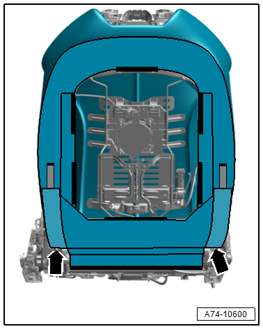
- Disengage the hooks on the backrest frame -arrows-.
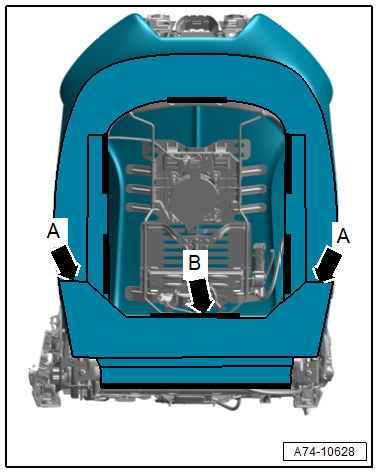
- Disengage the hooks from the cover -arrows A-.
- Disengage the lower molding from the backrest frame -arrow B-.
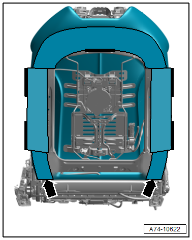
- Disengage the hooks for the side bolsters on the backrest frame -arrows-.
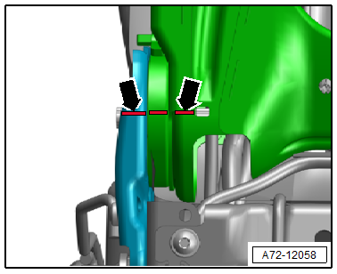
- Mark the left and right angle position of the backrest hinge to the backrest frame with paint -arrows-.
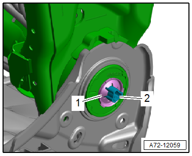
- Destroy the lock washer -1- and remove it.
- Push the adjustment shaft -2- to the opposite side out of the backrest frame.
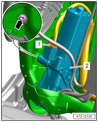
- Remove the bolt -arrow- and remove the backrest adjustment motor -2-.
- Disconnect the connector -1- from the removed backrest adjustment motor.
Installing
WARNING
Repairing pyrotechnic components (For example the airbag and seat belt tensioner) incorrectly increases the risk of unintentional deployments when the battery is connected.
- Pay attention to the safety precautions when working with pyrotechnic components. Refer to → Chapter "Safety Precautions when Working with Pyrotechnic Components".
- Before handling pyrotechnic components (For example, connecting a connector), the person handling it must "discharge static electricity". For example, this can be done by briefly touching the door striker.
- Follow all the instructions when installing the front seat. Refer to → Chapter "Front Seat, Removing and Installing".
- Check the left and right position of the backrest frame and hinge.
- The backrest frame must be in the position marked on the left and right side before removal -arrows-.
- If required, adjust the position accordingly.
- First slide the adjustment shaft through the anchor (tunnel side) as far as the mount in the backrest adjustment motor.
- Check if the profile of the inserted adjustment shaft and the mount in the backrest adjustment motor to see if they align.
- For adjustment, connect an external 12-volt power source to the backrest adjustment motor and turn mount until the profiles of adjustment shaft and mount are aligned.
- Slide the adjuster shaft through the mount in the backrest adjustment motor -2- and slide the hinge (side sill side) until it stops.
- Tighten the bolt -arrow- for the backrest adjustment motor.
Further installation is the reverse order of removal.
Installation instructions: For example tightening specifications, replacing components. Refer to → Chapter "Overview - Front Backrest, Backrest Adjustment Motor".
READ NEXT:
 Front Backrest, Removing and Installing
Front Backrest, Removing and Installing
Special tools and workshop equipment required
Engine/Transmission Holder - Seat Repair Fixture -VAS6136-
Caution
This procedure contains mandatory r
Headrest, Removing and Installing
Removing
- Set the backrest toward the rear at an angle.
- Grip the rear cover -1- at the
lower edge and push it upward out of the locking mechanism in
the direction of -arrows-.
- Mo
Seat Pan, Disassembling and Assembling
Front and Rear Seat Rail Cover, Removing and Installing
Removing
- Move the front seat into its highest position.
Caution
Risk of damaging the seat rail cover.
Proceed very carefully whe
SEE MORE:
General Information
Vehicles with a High Voltage System (Hybrid Vehicles)
Extremely Dangerous Due to High-Voltage
The high-voltage system is under high-voltage. Death or serious
bodily injury by electric shock.
- Individuals with electronic/medical life- and health sustaining
machines in or on their person canno
Rear Seat Entertainment System (RSE)
Overview - Rear Seat Entertainment System
The Rear Seat Entertainment System (RSE, 9WF) consists of:
Left Rear Information Display Control Head Control Module
-J648-/Right Rear Information Display Control Head Control
Module -J649- on the left/right front seat backrest frame
Information Electro
