Audi A4: ATF Circuit
Overview - ATF Circuit
 Caution
Risk of damaging the transmission.
- Remove all the plugs on the ATF lines and on the transmission that were installed during removal.
- The ATF cooling function will not work and the transmission will be damaged if the plugs are forgotten.
 WARNING
The system is under pressure.
- Deactivate the ATF pump and drain the hydraulic pressure reservoir before opening the ATF circuit!
- Refer to → Chapter "ATF Pump, Deactivating and Draining the Hydraulic Pump Reservoir".
ATF cooler, ATF line
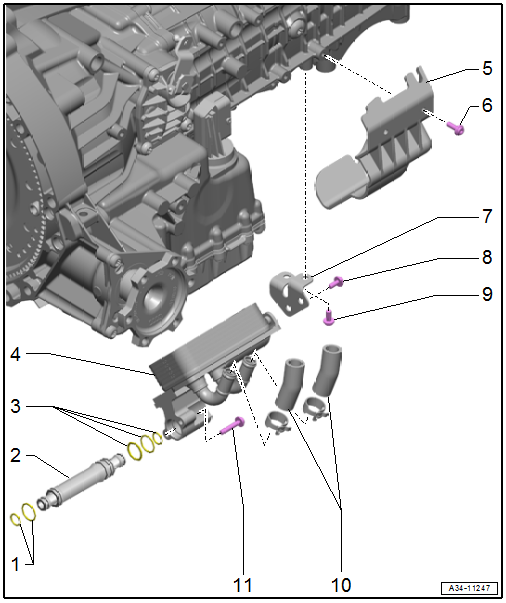
1 - O-Rings
- Replace after removing
2 - ATF Pipe
- Replace after removing
3 - O-Rings
- Replace after removing
4 - ATF Cooler
- Removing and installing. Refer to → Chapter "ATF Cooler, Removing and Installing".
5 - Guard Plate
- Depending on the version
6 - Bolt
- 8 Nm
7 - Bracket
8 - Bolt
- Tightening specification and sequence. Refer to → Fig. "ATF Cooler - Tightening Specification and Sequence".
9 - Bolt
- Tightening specification and sequence. Refer to → Fig. "ATF Cooler - Tightening Specification and Sequence".
10 - Coolant Hoses
11 - Bolt
- Tightening specification and sequence. Refer to → Fig. "ATF Cooler - Tightening Specification and Sequence".
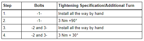
ATF Cooler - Tightening Specification and Sequence
- Tighten the bolts in steps according to the specified sequence:
Drain and Plug
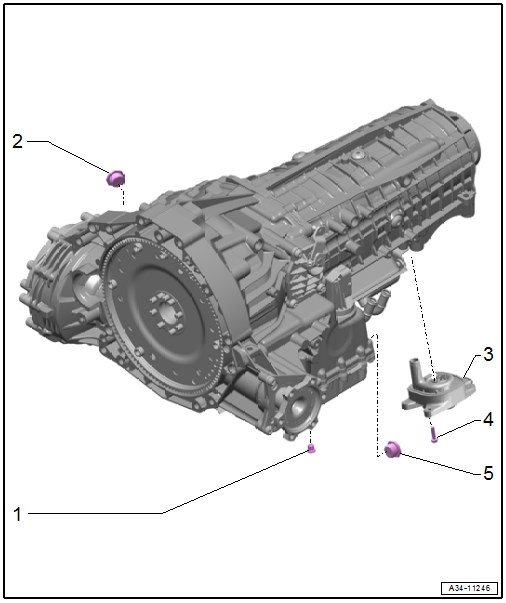
1 - Plug/Plugs
- Aluminum plug for the oil pan
- 8 Nm +30º
- Replace after removing
- Plastic plugs for the oil pan
- Tighten all the way
- For the ATF check and fill hole
2 - Plug
- For the transmission fluid inspection and fill hole
- Tightening Specification -item 2-
3 - Transmission Fluid Pump (MTF Pump)
- Must be removed for draining the transmission fluid (MTF). Refer to → Chapter "Transmission Fluid Pump, Removing and Installing".
4 - Bolt
- Tightening Specification -item 4-
5 - Plug/Plugs
- Aluminum plug for the oil pan
- 35 Nm
- Replace after removing
- Plastic plugs for the oil pan
- Tighten all the way
- For the ATF
ATF Cooler, Removing and Installing
Special tools and workshop equipment required
- Hose Clamps - Up To 25 mm -3094-
- Engine Bung Set -VAS6122-
- Hose Clip Pliers -VAS6362-
- Used Oil Collection and Extraction Unit -SMN372500-
Removing
WARNING
The system is under pressure.
Deactivate the ATF pump and drain the hydraulic pressure reservoir before removing the ATF cooler!
- Using the Vehicle Diagnostic Tester in the Transmission Control Module -J217- empty the ATF pressure reservoir and disable the Transmission Fluid Auxiliary Hydraulic Pump -V552-. Refer to → Chapter "ATF Pump, Deactivating and Draining the Hydraulic Pump Reservoir".
- Drain the ATF. Refer to → Chapter "ATF, Draining and Filling".
 Note
Note
To catch escaping coolant, place a cloth underneath.
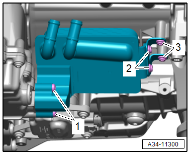
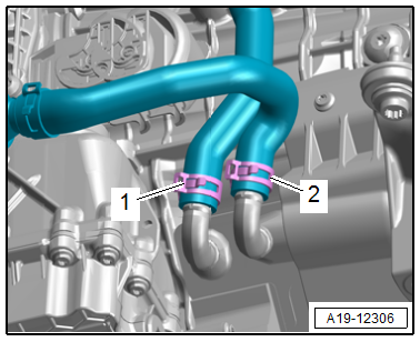
- Loosen the hose clamps -1 and 2- and then disconnect and remove the coolant hoses with Hose Clamps - Up To 25mm -3094-.
- Place the Used Oil Collection and Extraction Unit -SMN372500- underneath.
- Remove the bolts -1, 2 and 3- and the bracket.
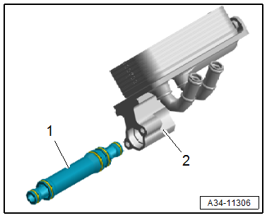
- Remove the ATF cooler -2- from the ATF pipe -1-.
- Seal the open lines and connections with clean plugs from the Engine Bung Set -VAS6122-.
- Remove the ATF pipe.
Installing
Install in the reverse order of removal while noting the following:
Note
- Replace the ATF line with seals after removing.
- Clean the ATF cooler before installing.
Caution
ATF cooler leak!
- Pay attention to the ATF pipe installation position.
- The side of the pipe with three seals faces the ATF cooler.
- Install the bolts all the way in by hand and tighten in the previously specified tightening sequence.
- Check the ATF level. Refer to → Chapter "ATF Level, Checking".
Tightening Specifications
- Refer to → Fig. "ATF Cooler - Tightening Specification and Sequence"
READ NEXT:
 Transmission Fluid
Transmission Fluid Level, Checking
Special tools and workshop equipment required
Torx Socket - T60 -T40087-
Protective Eyewear
Procedure
Note
General repair instructions. Refer to
→&n
ATF
ATF Level, Checking
Special tools and workshop equipment required
Vehicle Diagnostic Tester
Used Oil Collection and Extraction Unit -SMN372500-
Pressurized Gearbox Oil Filler Kit -VAS6617- with
P
Mechatronic
Overview - Mechatronic
1 - Transmission Fluid Pan
Removing and installing. Refer to
→ Chapter "Transmission Fluid Pan, Removing and Installing".
Aluminum or plastic
2 -&nbs
SEE MORE:
Stabilizer Bar
Overview - Stabilizer Bar
1 - Bolt
25 Nm + 90º
Replace after removing
Tighten in the curb weight position. Refer to
→ Chapter "Wheel Bearing in Curb Weight Position, Lifting Vehicles with
Coil Spring".
Tighten alternating in stages
2 - Clamp
3 - Stabili
Front Midrange Speaker, Removing and Installing
The Left Front Midrange Speaker -R103-/Right Front Midrange
Speaker -R104--1- are located in
the center of the front doors.
Removing and installing is identical.
Removing
- Turn off the ignition and all electrical equipment and
remove the ignition key.
- Remove the front door trim panel
