Audi A4: Control Module/Digital Sound System Amplifier, Removing and Installing
Special tools and workshop equipment required
- Fiber-Optic Repair Set - Connector Protective Caps -VAS6223/9-.
The Digital Sound System Control Module -J525--1- is located behind the left luggage compartment side trim panel.
 Note
Note
If replacing the control module, select the "Replace control module" function for the corresponding control module on the Vehicle Diagnostic Tester.
Removing
- Turn off the ignition and all electrical equipment and remove the ignition key.
- Open the left storage compartment in the luggage compartment.
The bracket with the Digital Sound System Control Module -J525- must be removed first.
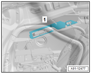
- Release and disconnect the connectors -1- from the Digital Sound System Control Module -J525--2-.
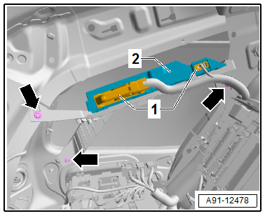
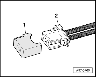
- Insert the Fiber-Optic Repair Set - Connector Protective Caps -VAS6223/9--1- onto the MOST Bus connector -2-.
- Remove the nuts -arrows- on the bracket and remove the Digital Sound System Control Module -J525--2- with the bracket.
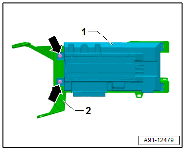
- Remove the bolts -arrows- and remove the Digital Sound System Control Module -J525--1- from the bracket -2-.
Installing
- Install in reverse order of removal. Note the following:
Tightening Specifications
- Refer to → Chapter "Component Location Overview - Sound System, Speaker, Sedan"
- Refer to → Chapter "Component Location Overview - Sound System, Speaker, Avant"
READ NEXT:
 Left and Right Rear Treble Speaker -R14-/-R16-, Removing and Installing
The Left Rear Treble Speaker -R14-/Right Rear Treble Speaker
-R16--1- are inside the rear doors
at the top.
Removing and installing is identical.
Removing
- Turn off the ignition and all electr
Front Midrange Speaker, Removing and Installing
The Left Front Midrange Speaker -R103-/Right Front Midrange
Speaker -R104--1- are located in
the center of the front doors.
Removing and installing is identical.
Removing
- Turn off the ignitio
Subwoofer -R211-, Removing and Installing
Subwoofer -R211-, Removing and Installing, Sedan
The Subwoofer -R211- is located in the rear shelf.
Removing
- Turn off the ignition and all electrical equipment and
remove the ignition key.
-&n
SEE MORE:
Selector Lever Handle, Removing and Installing
Note
Both the selector lever handle and the selector lever boot
are removed together.
Special tools and workshop equipment required
Trim Removal Wedge -3409-
Torque Wrench 1410 - VAG1410-
Removing
Ignition switched off.
- Remove the selector lever handle upper section
-1- upward
Changing a tire
Preparation
You must complete the preparation before
changing a tire.
Read and follow the important safety precautions.
Set the parking brake.
Select the "P" selector lever position.
When towing a trailer: disconnect the trailer
from your vehicle.
Lay out the vehicle tool kit and the
spare t
