Audi A4: Instrument Panel
Overview - Instrument Panel
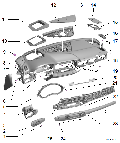
1 - Screw/Expanding Clip
- 1.5 Nm
2 - Light Switch Trim
- Removing and installing. Refer to → Chapter "Light Switch Trim, Removing and Installing".
- Press on until it engages audibly
3 - Bolts
- 3 Nm
- Quantity: 2
4 - Driver Side Instrument Panel Vent
- Removing and installing. Refer to → Chapter "Driver Side Instrument Panel Vent, Removing and Installing".
- Press on until it engages audibly
5 - Instrument Cluster Trim
- Removing and installing. Refer to → Chapter "Instrument Cluster Trim, Removing and Installing".
6 - Bolt
- 3 Nm
- Quantity: 3
7 - Instrument Panel Side Cover
- Removing and installing. Refer to → Chapter "Instrument Panel Side Cover, Removing and Installing".
- Press on until it engages audibly
8 - Bolt
- 3 Nm
- 9 - Rubber Buffer
- Quantity: 3
- Insert into the instrument panel mount at the bottom of the windshield frame
10 - Windshield Projection Frame
- Equipped on some models
- Removing and installing. Refer to → Electrical Equipment; Rep. Gr.90; Instrument Cluster; Overview - Windshield Projection (Head-Up Display).
11 - Windshield Projection Cover
- Equipped on some models
- Removing and installing. Refer to → Electrical Equipment; Rep. Gr.90; Instrument Cluster; Overview - Windshield Projection (Head-Up Display).
12 - Speaker in Center Trim
- Removing and installing. Refer to → Chapter "Speaker Trim, Removing and Installing".
- Press on until it engages audibly
13 - Front Center Defroster Vent
- Removing and installing. Refer to → Chapter "Front Center Defroster Vent, Removing and Installing".
- Press on until it engages audibly
14 - Outer Speaker Trim
- Removing and installing. Refer to → Chapter "Speaker Trim, Removing and Installing".
- Press on until it engages audibly
15 - Speaker Mount
- Removing and installing. Refer to → Chapter "Speaker Mount, Removing and Installing".
16 - Side Defroster Vent
- Removing and installing. Refer to → Chapter "Side Defroster Vent, Removing and Installing".
- Press on it until it locks
17 - Bolts
- 3 Nm
18 - Instrument Panel
 WARNING
Risk of injury due to involuntary deployment.
Pay attention to the safety precautions when working with pyrotechnic components. Refer to → Chapter "Safety Precautions when Working with Pyrotechnic Components".
- Removing and installing. Refer to → Chapter "Instrument Panel, Removing and Installing".
19 - Bolt
- 3 Nm
- Quantity: 4
20 - MMI Screen Cover
- Removing and installing. Refer to → Chapter "MMI Screen Cover, Removing and Installing".
- Press on until it engages audibly
21 - Bolt
- 3 Nm
- Quantity: 2
22 - Bolt
- 3 Nm
- Quantity: 6
23 - A/C Display Control Head Trim
- Removing and installing. Refer to → Chapter "Display Control Head Trim, Removing and Installing".
- Press on until it engages audibly
24 - Screw/Expanding Clip
- 1.5 Nm
- Quantity: 3
25 - Front Passenger Side Instrument Panel Vent
- Removing and installing. Refer to → Chapter "Passenger Side Instrument Panel Vent, Removing and Installing".
- Press on until it engages audibly
READ NEXT:
 Instrument Panel Side Cover, Removing and Installing
Special tools and workshop equipment required
Trim Removal Wedge -3409-
Removing
- Pry off the cover -1- for the
instrument panel side cover using the -3409- in the direction of
-arrow-.
-&nb
Instrument Panel, Removing and Installing
Removing
- Move the steering wheel as far to the rear and down as possible.
Use the full steering column adjustment range for this.
- Move the front seats all the way back and tilt backrest
Instrument Panel Vent, Removing and Installing
Driver Side Instrument Panel Vent, Removing and Installing
Special tools and workshop equipment required
Trim Removal Wedge -3409-
Removing
- Move the steering wheel as far up and backward as
SEE MORE:
ATF Circuit
Overview - ATF Circuit
Caution
Risk of damaging the transmission.
Remove all the plugs on the ATF lines and on the
transmission that were installed during removal.
The ATF cooling function will not work and the transmission
will be damaged if the plugs are forgotten.
WARNING
Overview - Sound System
The following systems are offered:
8RM - Basic sound system.
9VD - Standard sound system.
9VS - Premium sound system, Bang & Olufsen.
8RM - Basic Sound System
One speaker in the left and right front doors
One speaker on the left and right side of the instrument
panel
Two
