Audi A4: Instrument Panel, Removing and Installing
Removing
- Move the steering wheel as far to the rear and down as possible. Use the full steering column adjustment range for this.
- Move the front seats all the way back and tilt backrests 45º.
 WARNING
Risk of injury due to involuntary deployment.
Pay attention to the safety precautions when working with pyrotechnic components. Refer to → Chapter "Safety Precautions when Working with Pyrotechnic Components".
- Disconnect the battery ground cable with the ignition turned on. Refer to → Electrical Equipment; Rep. Gr.27; Battery; Battery, Disconnecting and Connecting.
- Remove the driver side airbag unit. Refer to → Chapter "Airbag Unit with Igniter, Removing and Installing".
- Remove the steering wheel. Refer to → Suspension, Wheels, Steering; Rep. Gr.48; Steering Wheel; Steering Wheel, Removing and Installing.
- Remove the upper steering column trim panel. Refer to → Chapter "Upper Steering Column Trim Panel, Removing and Installing".
- Remove the Switch Module in Instrument Panel, Center -EX22-. Refer to → Electrical Equipment; Rep. Gr.96; Controls; Component Location Overview - Instrument Panel Controls.
- Remove the center console. Refer to → Chapter "Center Console, Removing and Installing".
- Remove the instrument panel side cover. Refer to → Chapter "Instrument Panel Side Cover, Removing and Installing".
- Remove the instrument panel cover on the driver side. Refer to → Chapter "Driver Side Instrument Panel Cover, Removing and Installing".
- Remove the light switch trim. Refer to → Chapter "Light Switch Trim, Removing and Installing".
- Remove the glove compartment. Refer to → Chapter "Glove Compartment, Removing and Installing".
- Remove the A/C display control head trim. Refer to → Chapter "Display Control Head Trim, Removing and Installing".
- Remove the MMI screen cover. Refer to → Chapter "MMI Screen Cover, Removing and Installing".
- Remove the driver and front passenger instrument panel vent. Refer to → Chapter "Instrument Panel Vent, Removing and Installing".
- Remove the instrument cluster trim. Refer to → Chapter "Instrument Cluster Trim, Removing and Installing".
- Remove the instrument cluster. Refer to → Electrical Equipment; Rep. Gr.90; Instrument Cluster; Overview - Instrument Cluster.
- Remove the Infotainment system display. Refer to → Communication; Rep. Gr.91; Infotainment-System; Component Location Overview- Infotainment-System.
- Remove the center front defroster vent. Refer to → Chapter "Front Center Defroster Vent, Removing and Installing".
- Remove the center speaker in the instrument panel. Refer to → Communication; Rep. Gr.91; Sound System; Component Location Overview - Sound System.
- Remove the A-pillar upper trim panels. Refer to → Chapter "A-Pillar Trim Panel, Removing and Installing".
- Remove the mount for the Information Electronics Control Module 1 -J794-. Refer to → Communication; Rep. Gr.91; Infotainment System; Component Location Overview - Infotainment System.
- Remove the air duct to the right instrument panel vent and to the wide vent. Refer to → Heating, Ventilation and Air Conditioning; Rep. Gr.87; Air Duct; Overview - Passenger Compartment Air Ducts and Air Distribution.
WARNING
Risk of injury due to involuntary deployment.
Before handling pyrotechnic components (For example, disconnecting the connector), the person handling it must "discharge static electricity". For example, this can be done by briefly touching the door striker.
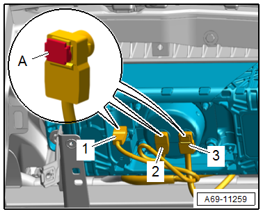
- Disconnect the connectors -1, 2 and 3- for the front passenger side airbag unit.
- Release the connector lock -A- using a small screwdriver.
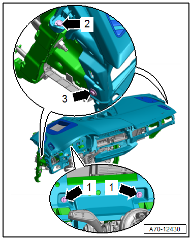
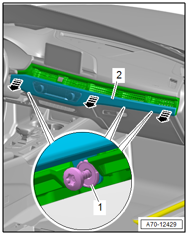
- Remove the instrument panel screws -arrows 1, 2 and 3- from the central tube.
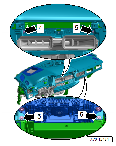
- Remove the instrument panel screws -arrows 4 and 5- from the central tube.
- Unclip and free up the wiring harnesses from the instrument panel.
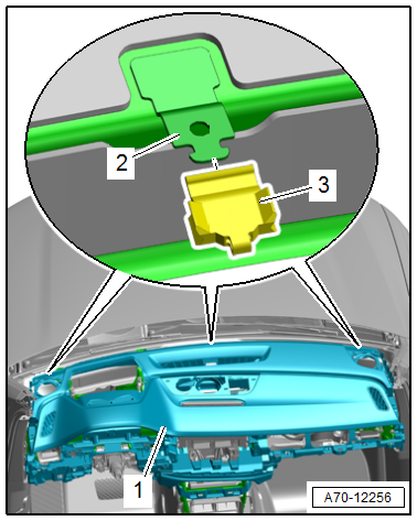
- Lift the instrument panel -1- slightly and carefully remove toward the rear from the mount -2- and from the central tube.
- Lift the instrument panel slightly and disconnect the connectors for the side speakers.
- Remove the instrument panel carefully toward the rear while guiding the connectors out.
- Remove the instrument panel from the vehicle interior and lay it on a soft surface.
Installing
Install in reverse order of removal and note the following:
 Note
Note
Pay attention to the allocation of the airbag to the instrument panel. Refer to the Parts Catalog.
- Set the instrument panel in place and guide the connectors through the openings in the instrument panel.
- Check if there is a rubber buffer -3- on the instrument panel mount -2- on the lower windshield frame.
- When sliding on the instrument panel -1-, make sure the instrument panel mounts engage in the box-shaped profiles on the bottom side of the instrument panel.
- Tighten the instrument panel screws in the sequence -arrows 1, 2 and 3-.
- Tighten the instrument panel screws in the sequence -arrows 4 and 5-.
WARNING
Risk of injury due to involuntary deployment.
- Pay attention to the safety precautions when working with pyrotechnic components. Refer to → Chapter "Safety Precautions when Working with Pyrotechnic Components".
- Before handling pyrotechnic components (For example, connecting a connector), the person handling it must "discharge static electricity". For example, this can be done by briefly touching the door striker.
Note
Make sure the connectors are pushed in all the way and that they engage audibly.
WARNING
Repairing pyrotechnic components (For example the airbag and seat belt tensioner) incorrectly increases the risk of injuries due to unintentional deployments when the battery is connected.
- The ignition must be on when connecting the battery.
- Make sure that no one is inside the vehicle at the time when the battery is connected.
- Connect the battery ground cable with the ignition switched on. Refer to → Electrical Equipment; Rep. Gr.27; Battery; Battery, Disconnecting and Connecting.
Note
If the Airbag Indicator Lamp -K75- indicates a fault, check the DTC memory, erase it and check it again using the Vehicle Diagnostic Tester.
Installation instructions: For example tightening specifications, replacing components. Refer to → Chapter "Overview - Instrument Panel".
Display Control Head Trim, Removing and Installing
Special tools and workshop equipment required
- Wedge Set -T10383-
- Wedge Set - Wedge 1 -T10383/1-
Removing
- Move the steering wheel as far up and backward as possible to be able to use the full steering column adjustment range.
- Remove the instrument panel cover on the driver side. Refer to → Chapter "Driver Side Instrument Panel Cover, Removing and Installing".
- Open the glove compartment lid and remove the expanding clips/screws -1-.
- Unclip the trim -2- with the A/C display control head using the Wedge Set - Wedge 1 -T10383/1- in the direction of -arrows-.
- Disconnect the connectors and remove the trim with the A/C display control head.
Installing
Install in reverse order of removal.
Installation instructions: For example tightening specifications, replacing components. Refer to → Chapter "Overview - Instrument Panel".
Speaker Mount, Removing and Installing
Special tools and workshop equipment required
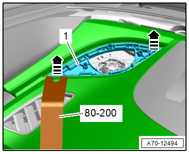
- Pry Lever -80-200-
- Trim Removal Wedge -3409-
Removing
- Remove the speaker trim. Refer to → Chapter "Speaker Trim, Removing and Installing".
- Carefully pry out the speaker mount -1- using the -80-200- in the direction of -arrows-.
- To do so, push the -3409- under the mount if necessary and carefully release the retaining pins.
Installing
Install in reverse order of removal.
Installation instructions: For example tightening specifications, replacing components. Refer to → Chapter "Overview - Instrument Panel".
READ NEXT:
 Instrument Panel Vent, Removing and Installing
Driver Side Instrument Panel Vent, Removing and Installing
Special tools and workshop equipment required
Trim Removal Wedge -3409-
Removing
- Move the steering wheel as far up and backward as
Instrument Panel Central Tube
Overview - Instrument Panel Central Tube
1 - Bolt
20 Nm
Quantity: 2
The mounting threads and contact surface must be free of paint, coating,
and corrosion. The threaded connection serv
Vehicle Interior Trim Panels
Component Location Overview - Vehicle Interior Trim Panels
Component Location Overview - Vehicle Interior Trim Panels, A3 Sedan
1 - D-Pillar Trim Panel
Overview. Refer to
→ Chapte
SEE MORE:
Automatic luggage compartment lid
Applies to: vehicles with automatic luggage compartment lid
Fig. 32 Luggage compartment lid: 1 closing button*, 2
lock button* (vehicles with convenience key*)
The luggage compartment lid can be opened and
closed automatically > in General information.
Opening the luggage compartment lid
When
Balance Shaft
Overview - Balance Shaft
1 - Cylinder Block
2 - Bolt
Tightening specifications. Refer to
→ Servicing - 4-Cylinder 2.0L 4V TFSI Engine; Rep. Gr.13; Balance Shaft;
Overview - Balance Shaft.
3 - Intake Side Balance Shaft
Removing and installing. Re
