Audi A4: Coolant System/Coolant
Connection Diagram - Coolant Hoses
Connection Diagram - Coolant Hoses, Versions without Parking Heater
 Note
Note
- Blue = large coolant circuit.
- Red = small coolant circuit.
- Brown = heating circuit.
- Green = coolant circuit for the transmission.
- The arrows show the coolant flow direction.
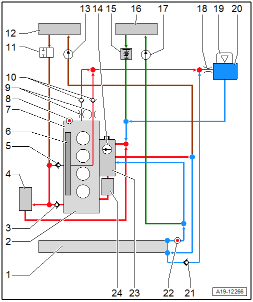
1 - Radiator
2 - Cylinder Block
3 - Check Valve
4 - Turbocharger
5 - Check Valve
6 - Exhaust Manifold
7 - Cylinder Head
8 - Engine Coolant Temperature Sensor -G62-
9 - Restrictors
10 - Check Valve
11 - Coolant Shut-Off Valve
- Controlled by a vacuum from the Climatronic Refrigerant Shut-Off Valve -N422-
12 - Heater Core for the Heater
13 - Coolant Recirculation Pump -V50-
14 - Coolant Pump
15 - Coolant Thermostat
- For transmission coolant circuit
- For versions with dual-clutch transmission
16 - ATF Cooler
- For versions with dual-clutch transmission
17 - After-Run Coolant Pump -V51-
- For versions with dual-clutch transmission
18 - Restrictor
19 - Cap
- Checking the pressure relief valve. Refer to → Servicing - 4-Cylinder 2.0L 4V TFSI Engine; Rep. Gr.19; Cooling System/Coolant; Cooling System, Checking For Leaks.
20 - Coolant Expansion Tank
21 - Check Valve
22 - Engine Coolant Temperature Sensor on Radiator Outlet -G83-
23 - Engine Temperature Control Actuator -N493-
24 - Engine Oil Cooler
Connection Diagram - Coolant Hoses, Versions with Parking Heater
Note
- Blue = large coolant circuit.
- Red = small coolant circuit.
- Brown = heating circuit.
- Green = coolant circuit for the transmission.
- The arrows show the coolant flow direction.
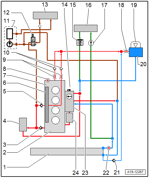
1 - Radiator
2 - Cylinder Block
3 - Check Valve
4 - Turbocharger
5 - Check Valve
6 - Exhaust Manifold
7 - Cylinder Head
8 - Engine Coolant Temperature Sensor -G62-
9 - Restrictors
10 - Check Valve
11 - Parking Heater
- With Recirculation Pump -V55-
12 - Heater Coolant Shut-Off Valve -N279-
13 - Heater Core for the Heater
14 - Coolant Pump
15 - Coolant Thermostat
- For transmission coolant circuit
- For versions with dual-clutch transmission
16 - ATF Cooler
- For versions with dual-clutch transmission
17 - After-Run Coolant Pump -V51-
- For versions with dual-clutch transmission
18 - Restrictor
19 - Cap
- Checking the pressure relief valve. Refer to → Servicing - 4-Cylinder 2.0L 4V TFSI Engine; Rep. Gr.19; Cooling System/Coolant; Cooling System, Checking For Leaks.
20 - Coolant Expansion Tank
21 - Check Valve
22 - Engine Coolant Temperature Sensor on Radiator Outlet -G83-
23 - Engine Temperature Control Actuator -N493-
24 - Engine Oil Cooler
Cooling System, Checking for Leaks
All procedures are described under: → Servicing - 4-Cylinder 2.0L 4V TFSI Engine; Rep. Gr.19; Cooling System/Coolant; Cooling System, Checking For Leaks.
Coolant, Draining and Filling
Special tools and workshop equipment required
- Coolant Collection System -VAS5014- or Shop Crane - Drip Tray -VAS6208-
- Hose Clip Pliers -VAS6362-
Draining
 WARNING
There is a risk of injury if the radiator fan turns on by itself.
The radiator fans can come on by itself even when the ignition is turned off, such as when heat builds up in the engine compartment.
Risk of scalding due to hot coolant.
Pay attention to the safety precautions. Refer to → Servicing - 4-Cylinder 2.0L 4V TFSI Engine; Rep. Gr.00; Safety Instructions; Safety Precautions when Working the Cooling System.
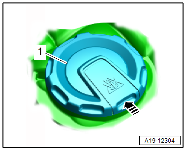
- Open the coolant expansion tank cap -1- by releasing the catch in the direction of -arrow-.
- Remove the front noise insulation. Refer to → Body Exterior; Rep. Gr.66; Noise Insulation; Overview - Noise Insulation.
- Place the container of the -VAS5014- or the -VAS6208- underneath.
- Remove the drain plug -1- on the connection and drain the coolant.
Note
Ignore item -2-.
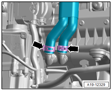
- Vehicles with dual-clutch transmission: Loosen the hose clamps -arrows-, remove the coolant hoses and let the coolant drain.
- Secure all hose connections with hose clamps that match the ones used in series production. Refer to the Parts Catalog.
- Tighten the drain plug and close the coolant hoses again.
Mix and Fill with Coolant
- Mix the coolant and fill. Refer to → Servicing - 4-Cylinder 2.0L 4V TFSI Engine; Rep. Gr.19; Cooling System/Coolant; Coolant, Draining and Filling.
Bleed Cooling System
- Remove the plenum chamber cover. Refer to → Body Exterior; Rep. Gr.50; Bulkhead; Plenum Chamber Cover, Removing and Installing.
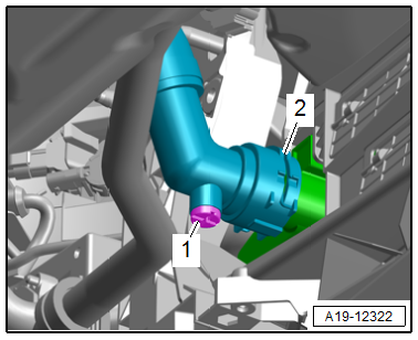
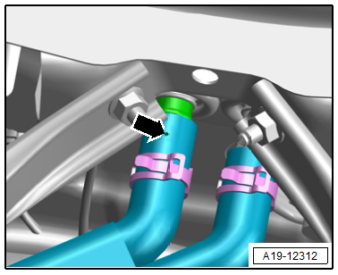
- Loosen the hose clamp -1- on the coolant hose to the heat exchanger and pull back the coolant hose until the connection no longer covers the bleeder hole -arrow-.
- Fill with coolant until it escapes from the coolant hose bleed hole.
- Slide the coolant hose onto the connection and secure with a spring clamp.
- Tighten the cap -1- on the coolant expansion tank until it locks into place.
- If the vehicle has a parking heater, switch it on for about 30 seconds.
- Start the engine.
.png)
- Turn off engine and allow it to cool off.
- Install the plenum chamber cover. Refer to → Body Exterior; Rep. Gr.50; Bulkhead; Plenum Chamber Cover, Removing and Installing.
Coolant Level, Checking
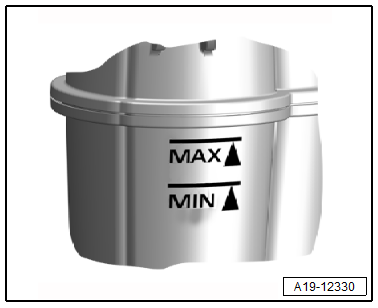
- Coolant level must be at "MAX" marking when the engine is engine cold.
- Coolant level may be above "MAX" marking with engine at operating temperature.
- If necessary, fill with coolant again.
Tightening Specifications
- Refer to → Chapter "Overview - Radiator/Radiator Fan"
- Refer to → Body Exterior; Rep. Gr.66; Noise Insulation; Overview - Noise Insulation.
READ NEXT:
 Coolant Pump/Coolant Thermostat
Overview - Coolant Pump/Coolant Thermostat
1 - Connection
2 - O-ring
Installation instructions. Refer to
→ Servicing - 4-Cylinder 2.0L 4V TFSI Engine; Rep. Gr.19;&n
Electric Coolant Pump, Removing and Installing
Coolant Recirculation Pump -V50-, Removing and Installing
Special tools and workshop equipment required
Hose Clamps - Up To 25mm -3094-
Hose Clip Pliers -VAS6340-
Removing
- Remove the engine
Coolant Pump, Removing and Installing
Removing
- Remove the engine cover. Refer to
→ Servicing - 4-Cylinder 2.0L 4V TFSI Engine; Rep. Gr.10; Engine
Cover; Engine Cover, Removing and Installing.
- Drain the coo
SEE MORE:
Trailer
Driving with a trailer
General information
Your vehicle is primarily intended for transporting
people and luggage. However, if you drive
with a trailer, follow the technical requirements,
the operation and driving tips, and the legal regulations.
Driving with a trailer affects the vehicle's energy
Adjusting adaptive cruise control
Applies to: vehicles with Audi adaptive cruise control
You can adjust the system individually. The settings
depend on the vehicle equipment.
Applies to: MMI: Select on the home screen:
VEHICLE > Driver assistance > Audi adaptive
cruise control.
Possible settings:
Applies to: vehicles with
