Audi A4: Effects Speaker, Removing and Installing
Left and Right Effects Speaker -R209-/-R210-, Removing and Installing, Sedan
Special tools and workshop equipment required
- Trim Removal Wedge -3409-
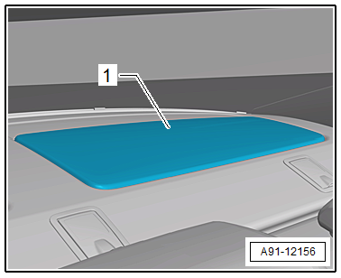
The Left Effects Speaker -R209-/Right Effects Speaker -R210- are located in the rear shelf.
Removing and installing is identical.
Removing
- Turn off the ignition and all electrical equipment and remove the ignition key.
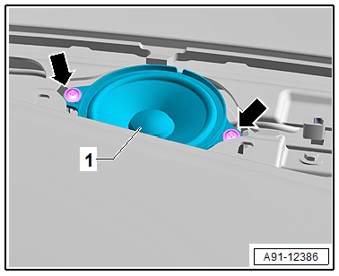
- Remove the speaker trim -1- from the rear shelf using the Trim Removal Wedge -3409-.
- Lift the speaker trim -1- until the connector on the Left Effects Speaker -R209- is accessible.
- Release and disconnect the connector from the Left Effects Speaker -R209-.
- Remove the speaker trim -1- with the Left Effects Speaker -R209-.
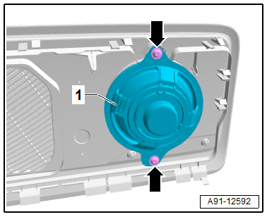
- Remove the bolts -arrows- from the Left Effects Speaker -R209--1-.
- Remove the Left Effects Speaker -R209--1- from the speaker trim.
Installing
- Install in reverse order of removal. Note the following:
Tightening Specifications
- Refer to → Chapter "Component Location Overview - Sound System, Speaker, Sedan"
Left and Right Effects Speaker -R209-/-R210-, Removing and Installing, Avant
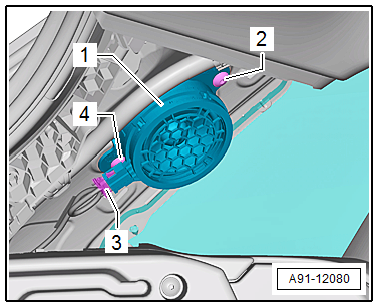
The Left Effects Speaker -R209-/Right Effects Speaker -R210- are located behind the D-pillar trim panels.
Removing and installing is identical.
Removing
- Turn off the ignition and all electrical equipment and remove the ignition key.
- Remove the D-pillar trim panel. Refer to → Body Interior; Rep. Gr.70; Vehicle Interior Trim Panels; Overview - D-Pillar Trim Panel.
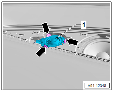
- Release and disconnect the connector -3- from the Left Effects Speaker -R209--1-.
- Remove the bolts -2 and 4- from the Left Effects Speaker -R209--1-.
- Remove the Left Effects Speaker -R209--1- from the D-pillar.
Installing
- Install in reverse order of removal. Note the following:
Tightening Specifications
- Refer to → Chapter "Component Location Overview - Sound System, Speaker, Avant"
Center Speaker, Removing and Installing
Center Speaker -R208-, Removing and Installing, 9VD/9VS
The Center Speaker -R208--3- is located in the center front of the instrument panel.
Removing
- Turn off the ignition and all electrical equipment and remove the ignition key.
- Remove the center defroster vent with the speaker trim. Refer to → Body Interior; Rep. Gr.70; Instrument Panel; Center Front Defroster Vent, Removing and Installing.
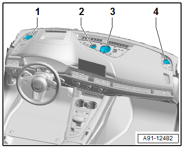
- Remove the bolts -arrows- on the Center Speaker -R208--1- and remove the Center Speaker -R208--1- upward.
- Release and disconnect the connector from the Center Speaker -R208--1-.
Installing
- Install in reverse order of removal. Note the following:
Tightening Specifications
- Refer to → Chapter "Component Location Overview - Sound System, Speaker, Sedan"
- Refer to → Chapter "Component Location Overview - Sound System, Speaker, Avant"
Center Speaker 2 -R219-, Removing and Installing, 9VS
Center Speaker 2 -R219--2- is located in the front center of the instrument panel.
Removing
- Turn off the ignition and all electrical equipment and remove the ignition key.
- Remove the center defroster vent with the speaker trim. Refer to → Body Interior; Rep. Gr.70; Instrument Panel; Center Front Defroster Vent, Removing and Installing.
- Press the tabs -arrows- on the Center Speaker 2 -R219--1- and remove the Center Speaker 2 -R219--1- upward.
- Release and disconnect the connector from the Center Speaker 2 -R219--1-.
Installing
- Installation is identical in reverse order of removal.
READ NEXT:
 Overview - Antenna Systems
Overview - Antenna Systems, Sedan, USA
The antenna systems consist of window antennas, a Roof
Antenna - R216- and bumper antennas.
Window Antennas
Antenna -R11- (AM/FM1)/TV Antenna 1 -R55- (TV1) to
Component Location Overview - Antenna Systems
Component Location Overview - Antenna Systems, Sedan, USA
1 - Antenna Amplifier -R24-
Removing and Installing. Refer to
→ Chapter "Antenna Amplifier -R24-, Removing and Installing
SEE MORE:
Sensors
Intake Air Temperature Sensor -G42-/Manifold Absolute Pressure Sensor
-G71-, Removing and Installing
All procedures are described under:
→ Servicing - 4-Cylinder 2.0L 4V TFSI Engine; Rep. Gr.24; Sensors; Intake Air
Temperature Sensor G42/Manifold Absolute Pressure SensorG71, Remo
Luggage compartment
General information
All pieces of luggage or objects must be securely
fastened in the luggage compartment. Note the
following to maintain good vehicle handling:
Distribute the load evenly in the luggage compartment.
Stow heavy luggage as far forward in the luggage
compartment as possible.
Use n
