Audi A4: Front Axle Camber, Centering
 Note
Note
- Camber cannot be adjusted.
- Camber can be centered evenly within specified tolerance range by shifting subframe.
Procedure
- Remove the noise insulation. Refer to → Body Exterior; Rep. Gr.66; Noise Insulation; Noise Insulation, Removing and Installing.
- Remove the left and right wheel spoilers. Refer to → Body Exterior; Rep. Gr.66; Wheel Housing Liner; Front Wheel Housing Liner, Removing and Installing.
 Caution
There is a risk of damaging the threads on the subframe threaded connection to the body.
- The subframe bolts on the body must not be loosened or tightened with an impact wrench.
- Always install all bolts by hand for the first few turns.
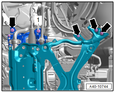
- Remove the left and right bolts -1 and arrows- for the subframe one after the other and replace.
- Install the new bolts all the way by hand.
Note
If the subframe is moved, the front of the vehicle must be lifted at the jack points using an axle lift.
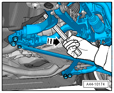
- Move the subframe with a plastic-coated pry bar into the corresponding position -arrow-.
- To do so place the pry bar in the center of the subframe near the control arm between the subframe and the body longitudinal member.
Note
If no plastic-coated pry bar is available, wrap a conventional pry bar with adhesive tape.
- The vehicle must be bounced several times at the front axle before checking the camber values.
- Axle alignment specified values. Refer to → Chapter "Axle Alignment Specified Values".
 WARNING
Risk of accident!
Replace the subframe bolts one after the other.
- Tighten the left and right subframe bolts diagonally in stages, and check the camber value again. Refer to → Chapter "Axle Alignment Specified Values".
Caution
There is a risk of adjustment errors.
All axle alignment values must be checked after every camber correction.
Tightening Specifications
- Refer to → Chapter "Overview - Subframe"
- Refer to → Body Exterior; Rep. Gr.66; Wheel Housing Liner; Overview - Front Wheel Housing Liner.
- Refer to → Body Exterior; Rep. Gr.66; Noise Insulation; Overview - Noise Insulation.
Front Axle Toe, Adjusting
Procedure
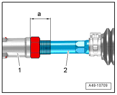
- Measure the dimension -a- between the tie rod head -1- and the left and right tie rod -2- and make a note of the value. Dimension -a- should be the same before and after adjusting on the left and right.
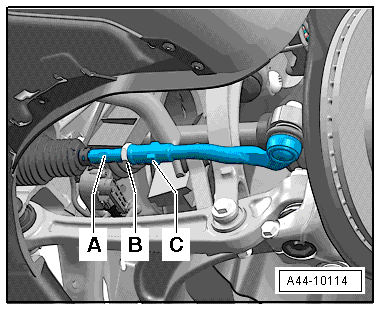
- Loosen the lock nut -B- by counterholding the tie rod end -C-.
- Adjust the toe respectively at the left and right wheel with the hex fitting -A-.
Caution
There is a risk of premature wear if the boot is twisted.
Be sure that boot is not twisted after turning tie rods.
- Tighten the lock nut -B--Item 5- → Item and check the toe-in value again.
Note
- After tightening the lock nut -B-, it is possible that the value will deviate slightly.
- However, if the measured toe value lies within the tolerance, the adjustment is correct.
Steering Angle Sensor -G85- Basic Setting
Special tools and workshop equipment required
- Vehicle Diagnostic Tester
- Steering Wheel Scales -VAS6458-
Procedure
Select this basic setting for the following operations:
- The Steering Column Electronics Control Module -J527- was replaced.
- The Active Steering Control Module -J792- was replaced,
- The steering column was replaced.
- Connect the Vehicle Diagnostic Tester.
- Switch the ignition on.
- Select and start the Diagnostic operating mode.
- Select the Test plan tab.
- Select the Select individual test button and select the following tree structure consecutively:
- Body
- Electrical system
- 01 - OBD-capable systems
- 16 - Steering column electronics control module J527
- 16 - Steering column electronics control module function
- 16 - Steering Angle Sensor G85
- Start the selected program and follow the instructions on the Vehicle Diagnostic Tester display.
READ NEXT:
 Dynamic Steering
Overview - Dynamic Steering
1 - Steering Gear
with Power Steering Control Module -J500-
2 - Electromechanical Power Steering Motor -V187-
Steering column component
Do not di
Adaptive Cruise Control (ACC)
Adaptive Cruise Control (ACC), Adjusting
Special tools and workshop equipment required
Vehicle Diagnostic Tester
Wheel Alignment Computer
Screwdriver with T-bar -VAS272001-, not illustrated
Setti
Driver Assistance Systems Front Camera
Driver Assistance Systems Front Camera, Calibrating
Special tools and workshop equipment required
Vehicle Diagnostic Tester
Wheel Alignment Computer
Setting Device Basic Set -VAS6430-
Setting Dev
SEE MORE:
Electric Coolant Pump, Removing and Installing
Coolant Recirculation Pump -V50-, Removing and Installing
Special tools and workshop equipment required
Hose Clamps - Up To 25mm -3094-
Hose Clip Pliers -VAS6340-
Removing
- Remove the engine cover. Refer to
→ Servicing - 4-Cylinder 2.0L 4V TFSI Engine; Rep. Gr.10; Engine
Seat Belt Latch, Function Test
Seat Belt Latch, Checking
- Insert the belt tongue into the seat belt latch until it clicks
into place. Check whether the locking mechanism is properly
engaged by giving the seat belt webbing a firm jerk.
Replace the entire seat belt with the seat belt latch if the
belt tongue fails even o
