Audi A4: Driver Assistance Systems Front Camera
Driver Assistance Systems Front Camera, Calibrating
Special tools and workshop equipment required
- Vehicle Diagnostic Tester
- Wheel Alignment Computer
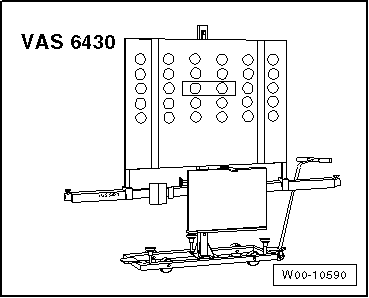
- Setting Device Basic Set -VAS6430-
- Setting Device - Basic Set -VAS6430/1A-
Requirements
- The -VAS6430/1A- must be set and locked in the center position.
- The Driver Assistance Systems Front Camera -R242- must fit correctly in the bracket.
- The view of the Driver Assistance Systems Front Camera -R242- must be clear.
- There are no entries in the Driver Assistance Systems Front Camera -R242- DTC memory.
There are two choices for calibrating:
The "quick access"
Select this procedure for the following operations if only the calibration should be performed:
- "No or incorrect basic setting/adaptation" is stored in the DTC memory.
- Removal and installation or replacement of the Driver Assistance Systems Front Camera -R242-.
- Removal and installation or replacement of the windshield,
The "complete alignment"
Select this procedure for the following operations if the calibration and a wheel alignment should be performed:
- The rear axle toe was adjusted.
- The vehicle suspension was changed, for example changing from standard to sport suspension.
 Note
Note
Both procedures are programmed in the wheel alignment computer. The respective procedure is performed automatically. It is only necessary to select the appropriate program for the procedure that will be performed.
Note the preparation work for calibrating assistance systems. Refer to → Chapter "Preparation Work for Calibrating and Adjusting Driver Assist Systems".
Calibrating without a previous axle alignment
- Select the front camera calibration procedure in the alignment computer.
- Attach the quick-action clamps to all four wheels.
- Mount the measurement sensor to the rear wheels.
- Perform a wheel run-out compensation on the rear wheels.
Calibrating with a previous axle alignment
- Connect the battery charger. Refer to → Electrical Equipment; Rep. Gr.27; Battery; Battery, Charging.
- Position the front wheels so they are straight.
- Connect the Vehicle Diagnostic Tester to the vehicle and guide the diagnostic cable through the open window.
- Turn off all vehicle exterior lamps.
- Close all vehicle doors.
Calibrating/adjusting procedure with or without a previous axle alignment
- Select the front camera calibration procedure in the alignment computer.
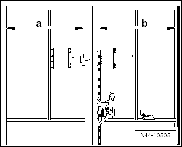
- Make sure the calibration board is positioned in the center and is locked in place.
- Dimension -a- = dimension -b-.
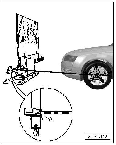
- Position the -VAS6430/1- at a distance of -A- 150 cm +- 2.5 cm (59 +- 0.98 inches) from the center of the wheel hub on the front wheels to the beam on the -VAS6430/1- as shown in the illustration.
Note
The -VAS6430/1A- must not be moved on the calibration beam.
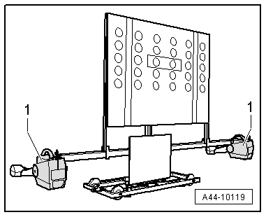
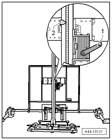
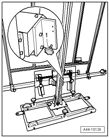
- Mount the front wheel measuring sensors -1- to the -VAS6430/1A-.
Note
The alignment stand must be in the lowest level position for the next step.
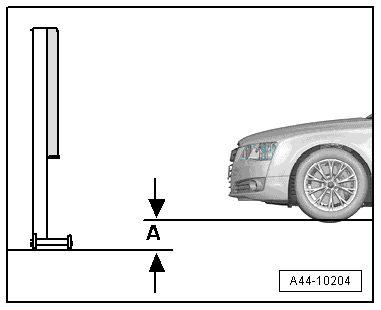
- Enter the height value -A- between the -VAS6430/1A- contact patch and the wheel contact surface as shown in the illustration and enter it in the alignment computer.
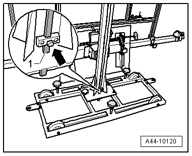
- Loosen the bolt -arrow- and place the measuring bar -1- on the floor.
- Adjust the calibration board to the specified height -2- according to the wheel alignment computer using the crank -1-.
If the specified height was reached -2-, then the measuring bar must be pushed slightly upward and secured with the clamping screw.
Note
If in later procedures the height of the calibration board must be corrected, make sure the measuring bar is touching the ground when this is being done.
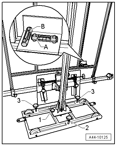
- Balance the bubble level -A- using the adjusting screw -1-.
The bubble level adjustment -A- serves to balance the ground conditions.
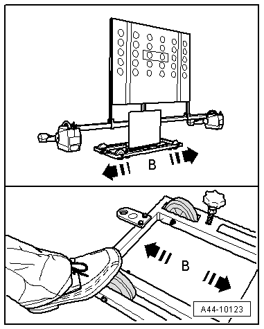
- Move the -VAS6430/1A- sideways in the direction of the -arrow B- until the display on the alignment computer is within the tolerance range.
- Secure the -VAS6430/1- by tightening the bolts -2 and 3- slightly. (This prevents the -VAS6430- from rolling away).
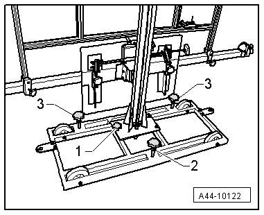
- Turn the fine adjustment screw -1- until the display on the wheel alignment computer is within the tolerance range.
- Balance the bubble level -A- using the adjusting screw -1-.
- Balance the bubble level -B- using the adjusting screw -2-.
Note
Because small height changes can result after adjusting the bubble levels, the height of the calibration board must be checked again.
Perform any subsequent work using the Vehicle Diagnostic Tester.
- Connect the Vehicle Diagnostic Tester.
- Switch the ignition on.
- Select and start the Diagnostic operating mode.
- Select the Test plan tab.
- Select the Select individual test button and select the following tree structure consecutively:
- Body
- 01 - OBD-capable systems
- A5 - Driver Assistance Systems Front Camera -R242
- A5 - Driver Assistance Systems Front Camera Functions
- A5 - Control module calibrating
- Start the selected program and follow the instructions on the Vehicle Diagnostic Tester display.
Note
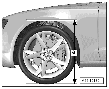
Next, determine the height of the body.
- Determine the body height -a- at all four wheels in the center of the wheel between the wheel contact surface and the lower edge of the fender or wheel housing.
Additional work, when the Driver Assistance Systems Front Camera -R242- is replaced:
- Adjust the headlamps. Refer to → Electrical Equipment; Rep. Gr.94; Headlamps; Headlamps, Adjusting.
Special Tools
Special tools and workshop equipment required
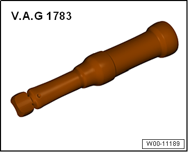
- Torque Wrench 1783 - 2-10Nm -VAG1783-
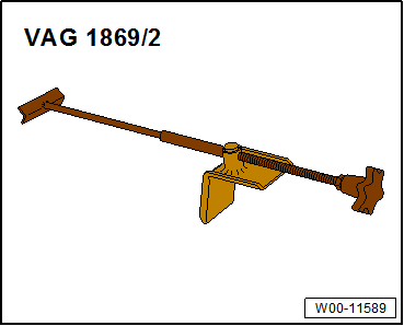
- Brake Pedal Actuator -VAG1869/2-.
- Setting Device - Basic Set -VAS6430/1- or Setting Device - Basic Set -VAS6430/1A-
- ACC Reflector Mirror - Audi -VAS6430/3-
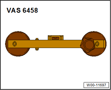
- Steering Wheel Scales -VAS6458-
- Not illustrated:
- Wheel Alignment Computer released by VW/Audi
- Screwdriver with T-bar -VAS272001-
READ NEXT:
 Steering Wheel
Overview - Steering Wheel
Overview - Steering Wheel, Three-Spoke Steering Wheel
1 - Bolt
Tightening specification. Refer to
→ Communication; Rep. Gr.91; Multifunction St
SEE MORE:
Solar Battery Maintainer -VAS6102A-
Solar Battery Maintainer -VAS6102A- Device Description
Solar Battery Maintainer -VAS6102A-
The Solar Battery Maintainer -VAS6102A- supports the vehicle
electrical system and prevents the Battery -A- from
self-discharging.
The Solar Battery Maintainer -VAS6102A- reaches a maximum
voltage of 14.3 V
Refrigerant R134a Characteristics
Commercial Names and Designations
Refrigerant R134a is currently available under the following
trade names:
H-FKW 134a
SUVA 134a
KLEA 134a
Note
Different trade names may be used in other countries.
Of the wide range of refrigerants available, this is the
only one which may be used
