Audi A4: Drive Axle, Removing and Installing
 Caution
This procedure contains mandatory replaceable parts. Refer to component overview and parts catalog prior to starting procedure.
Mandatory Replacement Parts
- Bolt - Outer CV Joint to Drive Axle
- Clamp - CV Boot to Outer CV Joint
- Clamp - CV Boot to Drive Axle
- Bolts - Backing Plate to CV Boot
- Circlip - Drive Axle
Removing
- Loosen the connection between the drive axle and wheel hub. Refer to → Chapter "Drive Axle Threaded Connection, Loosening and Tightening".
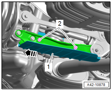
- Remove the expanding rivets -2-.
- Pull the wind deflector -1- slightly outward in the direction of the -arrow- and remove.
Left Side of the Vehicle
- Remove the rear muffler. Refer to → Rep. Gr.26; Exhaust Pipes/Mufflers; Overview - Muffler.
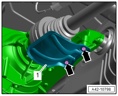
- Remove the bolts -arrows- and remove the heat shield -1-.
Continuation for All Vehicles
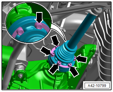
- Remove the bolts -arrows-, and carefully remove the drive axle.
 Note
Note
Be careful not to damage the protective coating on the drive axle.
Installing
Install in reverse order of removal and note the following:
- Tighten the threaded connection between the drive axle and wheel hub. Refer to → Chapter "Drive Axle Threaded Connection, Loosening and Tightening".
Tightening Specifications
- Refer to → Chapter "Overview - Drive Axle"
- Refer to → Fig. "Heat Shield - Tightening Specification"
Drive Axle Threaded Connection, Loosening and Tightening
Special tools and workshop equipment required
- Torque Wrench 80-400Nm -VAG1576-
- Socket AF 24 mm -T10361A-
Caution
This procedure contains mandatory replaceable parts. Refer to component overview and parts catalog prior to starting procedure.
Mandatory Replacement Parts
- Bolt - Outer CV Joint to Drive Axle
Loosen the threaded connection between the drive axle/stub axle and wheel hub
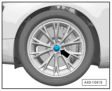
- With vehicle still resting on its wheels, loosen the bolt -arrow- a maximum of 90º using -T10361A-, otherwise the wheel bearing will be damaged.
- Lift the vehicle just enough so that the wheels are hanging free.
- Apply the brakes (a second technician required).
- Remove the bolt.
Tighten the threaded connection between the drive axle/stub axle and wheel hub
Note
- Replace bolt after removal.
- Before installing, clean the threads in the CV joint/stub axle with a thread tap.
- Wheels must not yet touch the ground when tightening the drive axle/stub shaft or the wheel bearing can be damaged.
- Apply the brakes (a second technician required).
- Tighten the bolt to 200 Nm.
- Set the vehicle on its wheels.
- Tighten the bolt an additional 180º.
READ NEXT:
 Drive Axle, Disassembling and Assembling
Drive Axle, Disassembling and Assembling, Outer CV Joint
Special tools and workshop equipment required
Locking ring pliers, commercially available
Sealant -D454 300 A2-. Refer to the Parts Catalog.
Inner CV Joint, Checking
It is necessary to disassemble the joint whenever replacing
the grease or if the ball surfaces show wear or damage.
Disassembling
Note
Ball hub and joint are paired and should be identified
Special Tools
Special tools and workshop equipment required
Engine/Gearbox Jack Adapter - Wheel Hub Support -T10149-
Hydraulic Press - Bushing Assembly Tool Kit -T10230-
Gearbox Support -T40173-
Pulle
SEE MORE:
Instrument Panel
Overview - Instrument Panel
1 - Screw/Expanding Clip
1.5 Nm
2 - Light Switch Trim
Removing and installing. Refer to
→ Chapter "Light Switch Trim, Removing and Installing".
Press on until it engages audibly
3 - Bolts
3 Nm
Quantity: 2
4 - Dri
Refrigerant Circuit, Charging with Service Station
Note
The entire refrigerant charge can be added to either the
high or low pressure side. Refer to
→ Chapter "Refrigerant R134a Capacities, Refrigerant Oil and
Approved Refrigerant Oils".
The work procedure is always to be performed as described in
the operating instructions for
