Audi A4: Drive Axle, Disassembling and Assembling
Drive Axle, Disassembling and Assembling, Outer CV Joint
Special tools and workshop equipment required
- Locking ring pliers, commercially available
- Sealant -D454 300 A2-. Refer to the Parts Catalog.
 Caution
This procedure contains mandatory replaceable parts. Refer to component overview and parts catalog prior to starting procedure.
Mandatory Replacement Parts
- Bolt - Outer CV Joint to Drive Axle
- Clamp - CV Boot to Outer CV Joint
- Clamp - CV Boot to Drive Axle
Outer CV Joint, Removing
- Clamp the drive axle in a vise with protective covers.
- Open clamps.
- Slide back the CV boot.
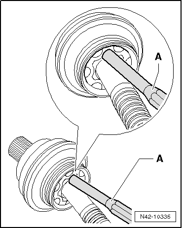
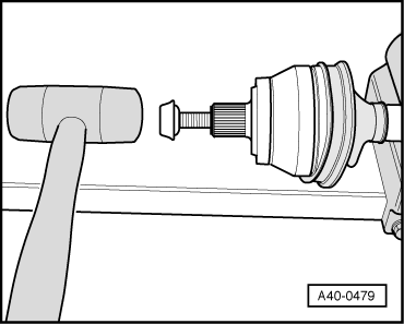
- Push the CV joint off of the drive axle using a drift -A-.
- The drift must be precisely positioned on the CV joint ball hub.
- Remove joint and CV boot.
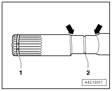
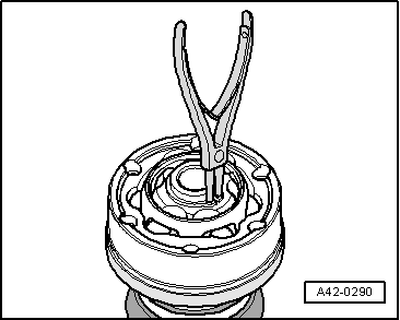
- Remove the circlip -1- with the locking ring pliers.
 Note
Note
Ignore item -2 and arrows-.
Outer CV Joint, Installing
- Push the CV boot and a new clamp onto the drive axle.
- The CV boot and the drive axle must be free of grease.
- Push on the CV boot between the -arrows- in the groove -2- until it engages.
- Apply and evenly distribute drive axle grease to the inside of the joint.
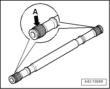
- Before installing the joint, the splines -arrow A- must be lightly coated with grease used in the joint.
- Insert the circlip into the groove on the shaft.
- Slide on the CV joint up to the circlip.
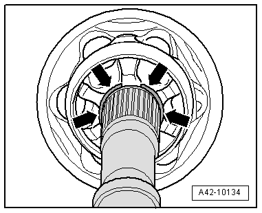
- Align the circlip at center with opening upward -arrows-.
- Install the old bolt in the joint as shown.
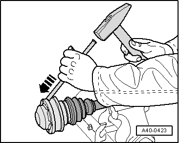
- Drive joint onto the drive axle with a plastic hammer until the circlip engages.
- Mount the CV boot on the metal cap.
- Bleed the CV boot.
- Make sure the CV boot is seated on the joint correctly.
- The CV boot must fit in the groove and on joint contour.
- Tension the clamps on the outer joint. Refer to → Fig. "Tension the Clamp using the Clamping Pliers -VAG1682A-.".
Drive Axle, Disassembling and Assembling, Inner CV Joint
Special tools and workshop equipment required
- Press Plate -VW401-
- Press Plate -VW402-
- Press Piece - Rod -VW409-
- Press Piece - Multiple Use -VW412-
- CV Joint Press Sleeve -VW522-
- Press Block -40-204A-
- Torque Wrench 1331 5-50Nm -VAG1331-
- Locking ring pliers, commercially available
- Sealant -D 454 300 A2-
Caution
This procedure contains mandatory replaceable parts. Refer to component overview and parts catalog prior to starting procedure.
Mandatory Replacement Parts
- Circlip - Drive Axle
- Clamp - CV Boot to Drive Axle
Inner CV Joint, Removing
- Clamp the drive axle horizontally in a vise with protective covers.
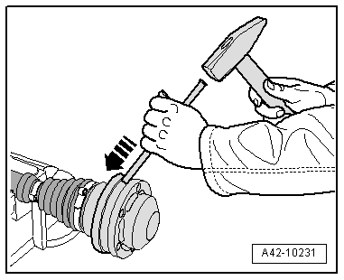
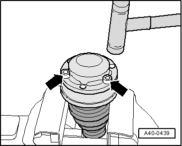
- Drive down the cover with a copper or brass mandrel -arrow-.
- Drive down the cap with a copper or brass mandrel -arrow-.
- Only open and remove the "small" CV boot clamp.
- Remove the circlip using the locking ring pliers.
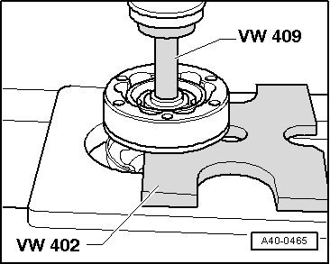
- Arrange the special tools as shown.
- Press the inner CV joint off of the drive axle.
- Remove the CV boot from the drive axle.
Inner CV Joint, Installing
- Slide the CV boot with the "small" clamp onto the drive axle.
- Before installing the joint, the splines -arrow A- must be lightly coated with grease used in the joint.
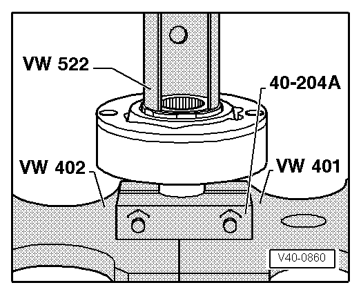
- Arrange the special tools as shown.
- The -40-204A- and clamping surfaces on drive axle must be free of grease.
- The chamfer on inner diameter of ball hub (splines) must face the contact shoulder on the drive axle.
- Press on joint until it stops.
- Install the new circlip using the locking ring pliers.
- Check the seating of the circlip.
- Apply half of the enclosed drive axle grease to the joint on the boot side before installing the CV boot.
- Grease the contact surfaces for the CV boot and cap.
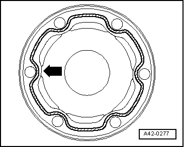
- Apply Sealant -D 454 300 A2--cross-hatched surface- on the clean surfaces on the inside of the CV boot cap.
- Sealant bead thickness: 2 to 3 mm.
- Apply the inner sealant bead near the holes -arrow-.
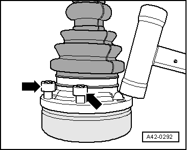
- Align the cap with bolts -arrows- with the bolt holes.
Note
It must be aligned exactly because it cannot be aligned after installing.
- Drive the cap on with a plastic mallet.
- Remove any excess sealant immediately.
- Apply the remaining drive axle grease through the ball races in the CV joint.
- Degrease the contact surfaces for the cover and for the CV joint.
- Apply Sealant -D 454 300 A2--cross-hatched surface- on the clean surface on the inside of the cover.
- Sealant bead thickness: 2 to 3 mm.
- Apply the inner sealant bead near the holes -arrow-.
- Align the new cover with bolts -arrows- to the bolt holes.
Note
It must be aligned exactly because it cannot be aligned after installing.
- Drive cover on with a plastic mallet.
- Clear away leaking sealing immediately.
- Push on the CV boot and position it in the groove -2- between the -arrows- on the drive axle.
Note
Ignore item -1-.
- Tighten clamps on inner joint. Refer to → Fig. "Tension the Clamp using the Clamping Pliers -VAG1682A-".
Outer CV Joint, Checking
- The outer CV joint and cap cannot be disassembled.
- Only a visual inspection may be performed on the outer CV joint and cap.
- The grease still in the joint must be free of water and dirt.
- If wear or damage is found on the ball journal surfaces, then the entire outer CV joint and cap must be replaced.
Grease quantities and types for the drive axle with outer CV joint.
READ NEXT:
 Inner CV Joint, Checking
It is necessary to disassemble the joint whenever replacing
the grease or if the ball surfaces show wear or damage.
Disassembling
Note
Ball hub and joint are paired and should be identified
Special Tools
Special tools and workshop equipment required
Engine/Gearbox Jack Adapter - Wheel Hub Support -T10149-
Hydraulic Press - Bushing Assembly Tool Kit -T10230-
Gearbox Support -T40173-
Pulle
SEE MORE:
Accessories and technical
changes
Warranty
Your vehicle is covered by various warranties:
New Vehicle Limited Warranty
Limited Warranty Against Corrosion Perforation
Emissions Control System Warranties: Federal
Emissions Control System Defect Warranty,
Federal Emissions Performance Warranty
Applies to: USA models: Kansas Safe
Fuel
Types of gasoline
The correct gasoline grade is stated on the inside
of the fuel filler door.
The vehicle is equipped with a catalytic converter
and must only be driven with unleaded gasoline.
Audi recommends using TOP TIER Detergent Gasoline.
For additional information on TOP TIER Detergent
Gasol
