Audi A4: Dynamic Steering
Overview - Dynamic Steering
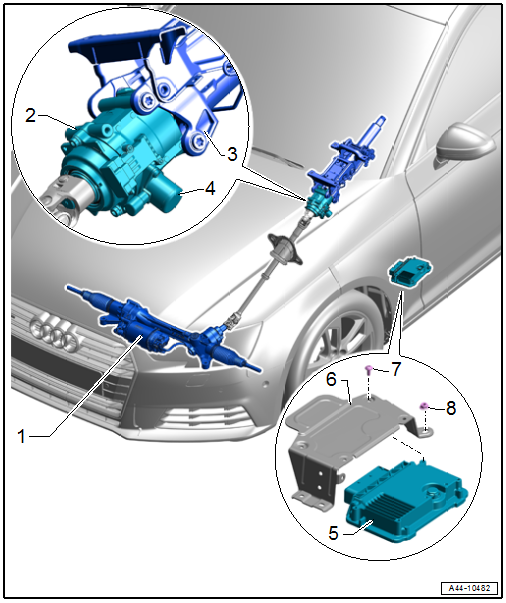
1 - Steering Gear
- with Power Steering Control Module -J500-
2 - Electromechanical Power Steering Motor -V187-
- Steering column component
- Do not disconnect or loosen from the steering column
- Replace the steering column if faulty. Refer to → Chapter "Steering Column, Removing and Installing".
3 - Steering Column
- Overview. Refer to → Chapter "Overview - Steering Column".
- Perform the basic setting after replacing. Refer to → Chapter "Dynamic Steering Basic Setting"
4 - Active Steering Safety Lock Actuator -F437-
- Removing and installing. Refer to → Chapter "Active Steering Safety Lock (Locking Solenoid), Removing and Installing".
5 - Active Steering Control Module -J792-
- Component location: in front of the driver seat
- Removing and installing. Refer to → Chapter "Active Steering Control Module -J792-, Removing and Installing".
- Perform the basic setting after replacing. Refer to → Chapter "Dynamic Steering Basic Setting"
6 - Bolt
- 8 Nm
7 - Nut
- 6 Nm
8 - Bracket
- For the Active Steering Control Module -J792-
Active Steering Control Module -J792-, Removing and Installing
Special tools and workshop equipment required
- Torque Wrench 1783 - 2-10Nm -VAG1783-
Removing
- Remove the footrest. Refer to → Body Interior; Rep. Gr.70; Vehicle Interior Trim Panels; Footrest, Removing and Installing.
- Remove the A-pillar lower trim panel. Refer to → Body Interior; Rep. Gr.70; Vehicle Interior Trim Panels; A-Pillar Trim Panel, Removing and Installing.
- Free up the left front carpet and lift up slightly.
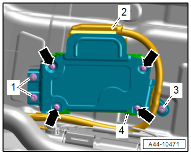
- Remove the bolts -arrows- and disconnect the connector -1-.
- Remove the Active Steering Control Module -J792--2-.
Installing
Install in reverse order of removal and note the following:
- Activate the control module after installing a new Active Steering Control Module -J792-.
- Connect the Vehicle Diagnostic Tester.
- Switch the ignition on.
- Select and start the Diagnostic operating mode.
- Select the Test plan tab.
- Select the Select individual test button and select the following tree structure consecutively:
- Chassis
- Suspension control
- 01 - OBD-capable systems
- 1B - Active Steering Control Module J792
- 1B - Active Steering Control Module functions J792
- 1B - Replacing the control module
- Start the selected program and follow the instructions on the Vehicle Diagnostic Tester display.
- The basic setting must be performed if the Active Steering Control Module -J792- was replaced. Refer to → Chapter "Dynamic Steering Basic Setting".
Tightening Specifications
- Refer to → Chapter "Overview - Dynamic Steering"
Dynamic Steering Basic Setting
Special tools and workshop equipment required
- Vehicle Diagnostic Tester
- Wheel Alignment Computer
Requirements
- Steering Angle Sensor -G85- is calibrated. Refer to → Chapter "Steering Angle Sensor -G85- Basic Setting".
- There are no entries in the DTC memory for the Active Steering Control Module -J792-.
Procedure
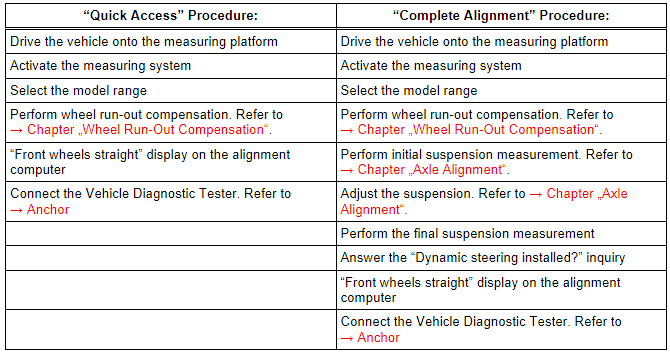
There are two choices for performing a basic setting on the dynamic steering:
The "quick access"
Select this procedure for the following operations if only the basic setting should be performed:
- The Steering Angle Sensor -G85- was calibrated.
- The Active Steering Control Module -J792- was replaced,
- The steering column was replaced.
- The steering wheel is crooked when driving straight.
The "complete alignment"
Select this procedure for the following operations if a basic setting and a wheel alignment should be performed.
- The front axle toe was adjusted.
- The rear axle toe was adjusted.
- The Steering Angle Sensor -G85- was calibrated.
- The Active Steering Control Module -J792- was replaced,
- The steering column was replaced.
- The steering wheel is crooked when driving straight.
- The vehicle suspension was changed, for example changing from standard to sport suspension.
Both procedures are programmed in the wheel alignment computer.
- The respective procedure is performed automatically.
- It is only necessary to select the appropriate program for the procedure that will be performed.
Preparation Work for Calibrating and Adjusting Driver Assist Systems. Refer to → Chapter "Preparation Work for Calibrating and Adjusting Driver Assist Systems".
- Select the basic setting procedure for dynamic steering in the alignment computer.
- Install the quick-action clamps on all four wheels.
- Install the measurement sensors on the front and rear wheels.
- Perform wheel run-out compensation. Refer to → Chapter "Wheel Run-Out Compensation".
 Note
Note
- Disregard the steering wheel position when doing this.
- Only the display on the wheel alignment computer applies.
Perform any subsequent work using the Vehicle Diagnostic Tester.
- Switch the ignition on.
- Select and start the Diagnostic operating mode.
- Select the Test plan tab.
- Select the Select individual test button and select the following tree structure consecutively:
- Chassis
- Steering
- 01 - OBD-capable systems
- 1B - Active Steering Control Module J792
- 1B - Active Steering Control Module functions J792
- 1B - Basic setting
- Start the selected program and follow the instructions on the Vehicle Diagnostic Tester display.
READ NEXT:
 Adaptive Cruise Control (ACC)
Adaptive Cruise Control (ACC), Adjusting
Special tools and workshop equipment required
Vehicle Diagnostic Tester
Wheel Alignment Computer
Screwdriver with T-bar -VAS272001-, not illustrated
Setti
Driver Assistance Systems Front Camera
Driver Assistance Systems Front Camera, Calibrating
Special tools and workshop equipment required
Vehicle Diagnostic Tester
Wheel Alignment Computer
Setting Device Basic Set -VAS6430-
Setting Dev
SEE MORE:
Antenna Amplifier, Removing and Installing
Antenna Amplifier -R24-, Removing and Installing, Sedan
The Antenna Amplifier -R24- is located on the upper right of
the D-pillar.
Removing
- Turn off the ignition and all electrical equipment and
remove the ignition key.
- Remove the D-pillar trim panel. Refer to
→ Body Interior;
Playing media
Media sources
The following sources can be selected depending
on the vehicle equipment:
Alexa
USB device
Connect external device: you can connect external
devices via Bluetooth and use the Bluetooth
audio player, or you can connect
an external device directly to the Audi music
interface
Str
